


Microvalve is one of the most important components in microfluidic systems and micropumps. In this paper, three-dimensional incompressible flow through a Tesla-type microvalve is simulated using FLUENT computational fluid dynamic package. The flow is laminar and SIMPLE algorithm is used. The second-order upwind method is implemented for discretizing convective terms. The diodicity mechanism is investigated in detail for three different microvalves. Effect of several series Tesla-type microvalves on diodicity is also studied. The numerical analyses reveal that the mechanism of diodicity occurs at the T-junction and side channel. If inlet and outlet channels are eliminated, diodicity can be increased by 2. Pressure field analysis shows that the pressure drop is much severe at the junction of the reverse flow compared to the forward flow. The obtained numerical results are compared with those of experimental and a good agreement between them is noticed.
valve hydraulic diameter
valve diodicity
characteristics length
pressure
pressure drop of forward flow
pressure drop of reverse flow
pressure drop independent of direction
position vector
Reynolds number
velocity
characteristic velocity of valve
Dynamic viscosity
density
MEMS (Micro-Electro-Mechanical Systems) devices often contain microfluidic systems that are designed to move very small quantities of fluid, such as microliters or even nanoliters, within the device. A micropump is one of the main devices in this field, which can generate flow in the range of milliliters to microliters. Today, a number of potential applications for micropumps are still being investigated, involving in drug delivery, biological detection, clinical analysis in medicine, cardiology system, etc. Microvalves can be classified into active microvalves, using mechanical and nonmechanical moving parts, and passive microvalves, using mechanical and non-mechanical moving parts [1]. Mechanical active microvalves employ the mechanically movable MEMS-based membranes which are coupled to magnetic [2], electric [3], piezoelectric [4] or thermal [5] actuation methods. The actuation principles of active microvalves with non-mechanical moving parts (NMP) are based on electrochemical [6], phase change [7], and rheological materials [8]. Non-mechanical passive microvalves (fixed microvalves) involve no mechanical moving parts and provide the possibility to build the so-called valveless micropumps. Two main types of fixed microvalves have been used in valveless micro- pumps which are microdiffusers and Tesla microvalves [9–10].
Using of microvalves results in increased performance, efficiency, reliability and reduced size and cost of the equipments. The first microvalve was introduced by Terry in 1978 [11]. The first commercial production started in 1990 and various types have been designed for different purposes up to now. One of the important applications of them is in heat control of electronic components at space equipments, such as micro-satellite [12]. Calibration, testing, measurement of volumes in micro-scale, mixing of microfluidic, etc. are other applications of microvalves [11–13–14]. In addition, microvalves are also used in medical applications. For example, they are used in the treatment of hydrocephalus. This system is located in the brain and causes the diversion of cerebrospinal fluid and may relieve symptoms [15–16].
There are a variety of NMP valve designs. Forster et al. [17] presented techniques for design and testing of fixed microvalves including the Tesla-type and the diffuser valve. The simplest configuration is shown in Figure 1, which is roughly similar to that designed in the macro-scale by Tesla. It has a bifurcated channel that re-enters the main flow channel perpendicularly when the flow is in the reverse direction. In the forward direction, the majority of the flow is carried by the main channel with reduced pressure losses. In a numerical study, Deshpande et al. [18] analyzed both Tesla and diffuser microvalves. Based on their study, Tesla microvalves are expected to provide higher diodicity capability than diffuser micro-valves. Morris and Forster [10] developed a model for Tesla-valve micropumps. Their model made it possible to determine optimal valve size. Bardell [19] developed a numerical method that accurately predicts the diodicity and reveals the diodicity mechanism of NMP microvalves using computational fluid dynamics package CFX 4.2.
![Tesla microvalve; a) in the forward direction, b) in the reverse direction [20]](https://static.elsevier.es/multimedia/16656423/0000001100000006/v2_201505081646/S1665642313715943/v2_201505081646/en/main.assets/gr1.jpeg?xkr=ue/ImdikoIMrsJoerZ+w997EogCnBdOOD93cPFbanNcX6PcOHo8VDqRKrp6xHZ/NlPxKUvo805ICrHlplwxcm7hYIESfjCCTNDlVokL+8rMDMXAS4ttiV2rgx4JPOvRbs3sRN1Z1en2AyJH/z/fTb6z3Yhjncc9d86HBAc/bqiCA23Vt69H5RDeBMQC94z97wQAvBY9OovNGC0ipY48vSDH3zul8URWtsBksw06bLOh85CsNbvBGlwktq8LCwSuylVyE+fiGi07HK04Bzn19qC85sWFRVsSHqoO4t4FEr14wOoA3P1m4NYtj1CmT6jULdYSTalvXY6RixUC9P3Je0w== "Tesla microvalve; a) in the forward direction, b) in the reverse direction [20]")
Tesla microvalve; a) in the forward direction, b) in the reverse direction [20]
The size of microvalves creates some difficulties in understanding their behavior through experimental procedures. The flow detection using particles with a diameter of around microns, can also affect the flow nature. Direct measurement of physical properties, such as pressure and flow rate is still impossible due to unavailability of micro-tools. Pressure transducers are at micro scale and they cannot be used in these systems, also pressure measurement using liquid column, changes the applied load on the system.
Therefore, using numerical methods will be useful in this case. The objective of this research is to develop a comprehensive understanding of the diodicity mechanism of three different Tesla-type NMP valve in low Reynolds numbers. FLUENT software is implemented to predict the diodicity and reveal the low Reynolds number diodicity mechanism of NMP valves. The numerical results are extensively validated with experimental ones.
2Flow geometryThe geometry of Tesla microvalve is shown in Figure 2. It is consisted of six regions: 1) inlet channel, 2) main channel, 3) side-channel, 4) T-junction, 5) Y-junction and 6) outlet channel

The ability of a microvalve to pass flow in the forward direction while inhibiting flow in the reverse direction is the diodicity of the valve. Since NMP valves have more resistance to flow in the reverse direction than in the forward direction, they produce a unidirectional net flow in the downstream direction even in the presence of a backpressure. The remaining portion of the instantaneous flow is the oscillatory slosh flow. In an electrical analogy, the instantaneous current is a sum of an alternating current (slosh flow) and a direct current (net flow). The diodicity, Di, is defined as
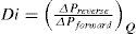
Eq. (1) is the ratio of pressure drop in back flow to the pressure drop in direct flow when the same flow rate passing through the valve at two cases. Due to the geometrical shape of these valves, the pressure drop in the back flow is higher than its value in direct flow, so that, the net flow is directed towards the straight direction. The diodicity for Tesla microvalves is usually small (1<Di<2) [19]. Pressure drop can be decomposed to independent and dependant smaller parts to flow direction.
Where, ΔPind, ΔPdep, rev and ΔPdep, for are pressure drop independent of direction, pressure drop dependent on flow direction and pressure drop dependent on flow direction in reverse flow, respectively. The above equation shows that pressure drop independent of the flow direction reduces the value of diodicity and, therefore, it should be minimized [19].3Governing equations
The flow equations are obtained by solving Navier-Stokes equations for incompressible, steady laminar flow. The dimensionless Navier-Stokes equations are as following,
Where, Dh, U and L are hydraulic diameter, characteristic speed and characteristic length, respectively.4Numerical simulation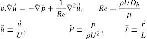
In inlet boundary, velocity is assumed to be constant and pressure is extrapolated from the field. At outlet boundary, the static pressure is assumed to be constant and other flow parameters such as velocity and temperature are determined by interpolation. No-slip condition is applied on the walls. In this simulation, because of cavitation limitations, we limited the pressure difference to ΔP<1 atm. The reverse flow calculation is done with ΔP=0.1, 0.5, 0.9atm. Mass flow passing through the microvalve with this pressure difference is recorded. Then, average pressure P¯Inlet is measured in inlet boundary and ΔPForward is calculated through ΔPForward=P¯Inlet−POutlet. These values are used in Eq. (1) and the diodicity is calculated. The computational fluid dynamic software FLUENT is implemented for simulation of three different Tesla microvalve. They include T45A, T45C and T45CDeep made by Stanford Nanofabrication Facility. Cooper type Hex/Wedge element is used to mesh the model as shown in Figure 3. The number of produced elements for T45A, T45C and T45CDeep is 324562, 379470 and 475592, respectively.

The error of diodicity is investigated to evaluate the mesh independence. The results show that by production of 324,562 elements with about 20% increase in number of elements, an error of about 5% is obtained in the diodicity, which is an acceptable result. The simulation is done by selection of laminar steady isothermal incompressible three-dimensional model. The segregated method is used to formulate continuity and momentum equations. Standard pressure method is used for interpolation of pressure. The second-order upwind method is used for discretization of momentum equation and SIMPLE algorithm is implemented for pressure-velocity coupling to solve Navier-Stokes equations. The iteration of calculations continued based on the velocity and mass continuity residuals until the dimensionless residuals reach to values lower than 10−5.
5Results and Discussion5.1Diodicity mechanism of T45AVelocity field at symmetric plane is shown in Figure 4 and Figure 5 for forward and reverse flows with Re = 528, respectively. It is obvious that the velocity field is severely different for forward and reverse flows. In the case of forward flow, the fluid is accelerated at the entrance of fluid from goblet-shaped plenum to the channel and velocity gradient is created. While, the flow is developing, it reaches into the T-junction. Some of the flow is drawn into the side-channel and a small jet is formed along the guide vane in the side-channel. However, about 85% of the main channel fully developed flow continues to its route without any disturbance (Figure 6). At this stage, as much as Tesla valve has ability to pass much more volume through the main channel, the diodicity will be higher.


The side-channel jet is expanded to the goblet section of the channel as a low-speed flow (as it gains 20% of the main channel maximum speed) and reaches to the Y-junction. However, it has enough momentum to divert the main channel flow before its reaching to the upper wall of Y-junction. It causes the diodicity improvement (Figure 7). The flow separation occurs at lower wall of Y-junction downstream and narrow jet of high velocity is formed near the upper wall (Figure 7). High velocity gradient between the jet and the wall causes additional losses and reduction in diodicity. Most parts of the channel are filled with low-speed areas, which narrowing these areas may be increase diodicity [19]. Finally, the flow is exited from the output channel and enters the goblet-shaped plenum.

In the case of reverse flow, the fluid accelerates at the entrance into channel from the goblet-shaped plenum and velocity gradients are created for reverse flow as the same for forward flow. While reaching to the Y-junction, slight flow will be diverted toward the main channel. When the flow reaches the cusp of guide vane less than half of the flow (about 35%) will be conducted to the main channel (near the guide vane wall) as shown in Figure 8, and most areas of the main channel are filled with low speed rotational areas. Unlike the previous condition, as the valve will be more capable to divert the flow to the side-channel, the diodicity will be higher.

The side-channel flow is separated from the upper wall and layer jet is formed along the guide vane wall. The jet is separated from the guide vane at goblet of side-channel, and it is connected to the upper wall of side-channel (Figure 9). The layer jet is leading towards the lower wall of the main channel, in a way that it is exited from the side-channel. But, the momentum of smaller flow coming from main channel, reveres it direction before the jet can reach the opposite wall (Figure 10). A severe rotational region is formed downstream of the T-junction (Figure 10). However, jet is dissipated at the entrance channel and fills the inlet of the channel.


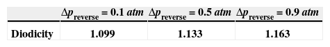
Pressure field in the cases of forward and reverse flow with Re = 528 at symmetric plane are depicted in Figures 11 and 12, respectively. Unlike the forward and reverse velocity fields, pressure fields have similarities which are partially due to the geometric symmetry at both the inlet and outlet of the valve. The considerable pressure loss regardless of the direction of flow occurs at the entrance of channel. In fact, one of the main sources of pressure loss is in both flow directions. Furthermore, there is a significant source of pressure loss in each direction: During the forward flow at the 45-degree knee and at downstream of the T-junction during reverse flow. Studies on the pressure field show that the pressure loss in 45-degree knee is about 0.1atm in forward flow and is about 0.2atm at downstream of the T-junction in reverse flow. This is the main factor in calculation of diodicity. Therefore, by using diodicity equation, the diodicity will increase from 1.2 to 2 if the losses independent from the flow direction are removed at channel inlets. But the problem is that they cannot be completely eliminated, and the channel's inlet and outlet should be adjusted in a way that inlet losses in forward flow will be less than the reverse flow. Table 1 shows the values of diodicity for T45A microvalve at different conditions.


The difference between T45C and T45A is the angle of main and side channel at T-junction. The angle is higher for T45A and the length of channel is lower. Velocity and pressure fields at symmetric plane are shown in Figure 13 and Figure 14 for forward flow with Re = 519, respectively.


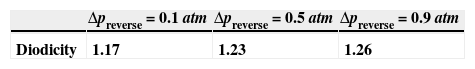
In this model, due to variation in the angle between side and main channels, a higher amount of flow rate passes through the main channel in forward flow. Velocity and pressure fields at symmetric plane are shown in Figure 15 and Figure 16 for reverse flow with Re = 519, respectively. Table 2 shows the values of diodicity for T45C microvalve at different conditions.


In this model, due to variation in the angle between side and main channels, effect of laminar jet losses and creation of stronger rotational regions, the pressure loss is higher in reverse flow.
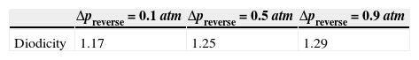
5.3Diodicity mechanism of T45CdeepThe only difference between T45C and T45Cdeep is their depth. The average depth of it is 115 and 148.3 micrometers, respectively. Velocity and pressure fields at symmetric plane are shown in Figure 17 and Figure 18 for forward flow with Re = 558.8, respectively.


Velocity and pressure fields at symmetric plane are shown in Figure 19 and Figure 20 for reverse flow with Re = 558.8, respectively. Table 3 shows the values of diodicity for T45CDeep microvalve at different conditions.


The experimental results of four T45A, four T45C and two T45CDeep microvalves [19] are compared with the results of obtained numerical simulation and a good agreement between them is noticed as shown in Figures 21, 22 and 23, respectively.


According to the results obtained in previous section, we choose T45A-2 microvalve in order to study the effect of series Tesla microvalves on diodicity mechanism. The T45A-2 microvalve with 1,2,3,4 and 5 elements at pressure differences of 0.5, 0.7 and 0.9atm is taken into account. The results are represented in Figure 24. It can be observed that by increasing the number of elements there is a nonlinear relationship between the number of microvalves and diodicity. The slope of diodicity increasing is high in the beginning but after the third valve it becomes much less and after the fourth valve it approximately reaches to zero. By increasing the valve elements, although the pressure loss increases in forward flow, pressure loss of reverse flow increases as well.

It is evident that slope reduction is lower at high pressure differences. The improvement in diodicity at high pressure differences is due to higher momentum of fluid and further increase in reverse flow losses which are directly proportional to the square of velocity. Velocity field at symmetric plane is shown for three and five-element T45A-2 microvalves in Figure 25 to Figure 28 in forward and reverse flow with Δp=0.5atm, respectively.


In this paper, diodicity mechanism is investigated in a side-channel and T-junction of different Tesla-type microvalves by using FLUENT CFD package. Other parts of the valve have slight diodicity effect and result in slight increase in overall valve diodicity. If there is no need to inlet and outlet flow channels, the overall diodicity can be increased up to 2. Velocity field show that in forward flow a jet is formed in outlet channel and one is formed in inlet channel in reverse flow, but, the laminar jet of direct flow is weaker and is at the downstream of the cusp, while the jet is stronger without cusp, therefore, the energy loss is more severe in the surrounding area. The pressure field indicated that pressure drop at Y-junction is much severe in reverse flow. If you consider a complete valve, about two-thirds of the pressure work is lost and only a third of it is converted to the energy flux, So, The viscosity effects overcome the inertia effects at low Reynolds number in these microvalves. Furthermore, by increasing the number of valves and pressure difference, diodicity increases.