


This paper presents the design and analysis of a transformer based 36-pulse ac-dc converters which supplies direct torque controlled induction motor drives (DTCIMD's) in order to have better power quality conditions at the point of common coupling. The converters output voltage is accomplished via two paralleled eighteen-pulse ac-dc converters each of them consisting of nine-phase diode bridge rectifier. The design procedure of magnetics is in a way such that makes it suitable for retrofit applications where a six-pulse diode bridge rectifier is being utilized. The 36-pulse structure improves power quality criteria at ac mains and makes them consistent with the IEEE-519 standard requirements for varying loads. Furthermore, near unity power factor is obtained for a wide range of DTCIMD operation. A comparison is made between 6-pulse and 36-pulse converters (Polygon, Fork, and Hexagon) from view point of power quality indices. Results show that input current total harmonic distortion (THD) is less than 4% for the 36-pulse topologies at variable loads. The Delta/Hexagon connected platform could simplify the resulted configuration for the converters and reducing the costs.
Recent advances in solid state conversion technology has led to the proliferation of variable frequency induction motor drives (VFIMD's) that are used in several applications such as air conditioning, blowers, fans, pumps for waste water treatment plants, textile mills, rolling mills etc [1]. The most practical technique in VFIMD's is direct torque controlled strategy in that it offers better performance rather than the other control techniques. Direct Torque controlled technique is implemented in voltage source inverter which is mostly fed from six-pulse diode bridge rectifier, Insulated gate bipolar transistors (IGBT's) are employed as the VSI switches. The most important drawback of the six-pulse diode-bridge rectifier is its poor power factor injection of current harmonics into ac mains. The circulation of current harmonics into the source impedance yields in harmonic polluted voltages at the point of common coupling (PCC) and consequently resulting in undesired supply voltage conditions for costumers in the vicinity. The value of current harmonic components which are injected into the grid by nonlinear loads such as DTCIMD's should be confined within the standard limitations. The most prominent standards in this field are IEEE standard 519 [2] and the International Electrotechnical Commission (IEC) 61000-3-2 [3].
According to considerable growth of Static Power Converters (SPC's) that are the major sources of harmonic distortion and as a result their power quality problems, researchers have focused their attention on harmonic eliminating solutions. For DTCIMD's one effective solution is to employ multipulse AC-DC converters. These converters are based on either phase multiplication or phase shifting or pulse doubling or a combination [4-19]. Although, in the conditions of light load or small source impedance, line current total harmonic distortion (THD) will be more than 5% for up to 18-pulse AC-DC converters. A Hexagon-Connected Autotransformer-Based 24-pulse AC-DC converter is reported in [7] which has THD variation of 4.48% to 5.65% from full-load to light-load (20% of full-load). A Zigzag-Connected Autotransformer-Based 24-pulse AC-DC converter is reported in [13] which has THD variation of 4.51% to 5.77% from full-load to light-load (20% of full-load).
Another T-Connected Autotransformer-Based 24-Pulse AC-DC Converter has also been presented in [14], however, the THD of the supply current with this topology is reported to vary from 2.46% to 5.20% which is more than 5% when operating at light load. The 36-pulse one was designed for vector controlled induction motor drives in [17] which has THD variation of 2.03% to 3.74% from full-load to light-load (20% of full-load) respectively but the dc link voltage is higher than that of a 6-pulse diode bridge rectifier, thus making the scheme nonapplicable for retrofit applications.
The delta/polygon-connected transformer-based 36-pulse ac-dc converter (shown in Fig. 1) for power quality improvement in [18] which has THD variation of 2.92% to 3.89% from full-load to light- load (20% of full-load) respectively and Delta/Fork-Connected Transformer-based 36-pulse ac–dc converter (shown in Fig. 2) have been reported [19] for reducing the total harmonic distortion (THD) of the ac mains current. But these topologies require higher rating magnetics, resulting in the enhancement of capital cost. As is mentioned before, the Delta/Hexagon connected platform could simplify the resulted configuration for the converters and reducing the costs (shown in Fig. 3). The Delta/Hexagon scheme has an optimized configuration in this regard. The proposed design method will be suitable even when the transformer output voltages vary while keeping its 36-pulse operation. In the 36-pulse structure, two nine-leg diode-bridge rectifiers are paralleled via two interphase transformers (IPTs) and fed from a transformer. Hence, a 36-pulse output voltage is obtained. Detailed design tips of the IPT and totally the whole structure of 36-pulse ac–dc converter are described in this paper and the proposed converter is modeled and simulated in MATLAB to study its behavior and specifically to analyze the power quality indices at ac mains. Furthermore, a 36-pulse ac–dc converter consisting of a delta/hexagon transformer, two eighteen-pulse diode bridge rectifiers paralleled through two IPTs, and with a DTCIMD load Fig. 3.
![Transformer configuration, Winding arrangement, and Phasor representation of trans former for 36-pulse AC-DC converter having delta/Polygon connected secondary winding [18].](https://static.elsevier.es/multimedia/16656423/0000001300000001/v1_201504070131/S1665642315300122/v1_201504070131/en/main.assets/gr1.jpeg?xkr=ue/ImdikoIMrsJoerZ+w997EogCnBdOOD93cPFbanNcX6PcOHo8VDqRKrp6xHZ/NlPxKUvo805ICrHlplwxcm7hYIESfjCCTNDlVokL+8rNVUGNYYzbmRa0TGSCLYpZPwm9NGBFdLxbWbLR/90lVASGl4sG3fLFCfzRDTKOYAaG0ZpAcPjGLmBMU8ZM1AOB6llxisV8a7J5Fpwb9oRtihFJWtI1y4RYs50fGaYoMy3VImlqwHvE9ZlDOSoQeMydq9PAWebJvDCingArLc4p2Fk6EEDKqQui5hXnCTkK2s26dppTnTlMJ55pKvcVUfOlh0QYFx5HpLlaAyRHuQTlQbQ== "Transformer configuration, Winding arrangement, and Phasor representation of trans former for 36-pulse AC-DC converter having delta/Polygon connected secondary winding [18].")
Transformer configuration, Winding arrangement, and Phasor representation of trans former for 36-pulse AC-DC converter having delta/Polygon connected secondary winding [18].
![Transformer configuration, Winding arrangement, and Phasor representation of transformer for 36-pulse AC–DC converter havin g delta/fork connected secondary winding [19].](https://static.elsevier.es/multimedia/16656423/0000001300000001/v1_201504070131/S1665642315300122/v1_201504070131/en/main.assets/gr2.jpeg?xkr=ue/ImdikoIMrsJoerZ+w997EogCnBdOOD93cPFbanNcX6PcOHo8VDqRKrp6xHZ/NlPxKUvo805ICrHlplwxcm7hYIESfjCCTNDlVokL+8rNVUGNYYzbmRa0TGSCLYpZPwm9NGBFdLxbWbLR/90lVASGl4sG3fLFCfzRDTKOYAaG0ZpAcPjGLmBMU8ZM1AOB6llxisV8a7J5Fpwb9oRtihFJWtI1y4RYs50fGaYoMy3VImlqwHvE9ZlDOSoQeMydq9PAWebJvDCingArLc4p2Fk6EEDKqQui5hXnCTkK2s26dppTnTlMJ55pKvcVUfOlh0QYFx5HpLlaAyRHuQTlQbQ== "Transformer configuration, Winding arrangement, and Phasor representation of transformer for 36-pulse AC–DC converter havin g delta/fork connected secondary winding [19].")
Transformer configuration, Winding arrangement, and Phasor representation of transformer for 36-pulse AC–DC converter havin g delta/fork connected secondary winding [19].

Simulation results of six-pulse and proposed 36-pulse ac–dc converters feeding a DTCIMD load are scheduled and various quality criteria such as THD of ac mains current, power factor, displacement factor, distortion factor, and THD of the supply voltage at PCC are compared.
2Proposed 36-Pulse AC–DC ConverterIn order to implement a 36-pulse ac–dc converter through paralleling two bridge rectifiers, i.e. two 18-pulse rectifiers, two sets of nine-phase voltages with a phase difference of 40 degrees between the voltages of each group and 10 degrees between the same voltages of the two groups are required.
Accordingly, each bridge rectifier consists of nine common-anode and nine common-cathode diodes (two nine-leg rectifiers). Phasor diagram of delta/hexagon transformer is shown in Fig. 4.

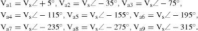
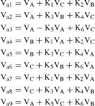
The hexagon transformer winding arrangement for 36-pulse AC–DC conversion is shown in Fig. 5 and its connection along with phasor diagram. The aforementioned two voltage sets are called as (Va1, Va2, Va3, Va4, Va5, Va6, Va7, Va8, Va9) and (Vb1, Vb2, Vb3, Vb4, Vb5, Vb6, Vb7, Vb8, Vb9) that are fed to rectifiers I and II, respectively. The same voltages of the two groups, i.e. Vai and Vbi, are phase displaced of 10 degrees. V¬a1 and Vb1 has a phase shift of +5 and -5 degrees from the input voltage of phase A, respectively. According to phasor diagram, the nine-phase voltages are made from ac main phase and line voltages with fractions of the primary winding turns which are expressed with the following relationships. Consider three-phase voltages of primary windings as follows:


Where, nine-phase voltages are:

Input voltages for converter I are:
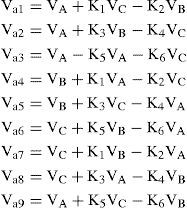
Input voltages for converter II are:

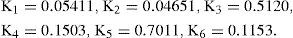
Constants K1-K6 are calculated using (2)–(6) to obtain the required windings turn numbers to have the desired phase shift for the two voltage sets:
Heading: numbered sequentially in Arabic numerals, left justified, in 10-point Arial Italics font, upper and lower case letters.
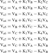
2.2Design of Transformer for Retrofit ApplicationsThe value of output voltage in multipulse rectifiers boosts relative to the output voltage of a six-pulse converter making the multipulse rectifier inappropriate for retrofit applications. For instance, with the transformer arrangement of the proposed 36-pulse converter, the rectified output voltage is 17% higher than that of six-pulse rectifier. For retrofit applications, the above design procedure is modified so that the dc-link voltage becomes equal to that of six-pulse rectifier. This will be accomplished via modifications in the tapping positions on the windings as shown in Fig. 6. It should be noted that with this approach, the desired phase shift is still unchanged. Similar to section II part 1, the following equations can be derived as:

Input voltages for converter I are:
Input voltages for converter II are:

Accordingly, the values of constants K1-K6 are changed for retrofit applications as:

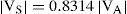
The values of K1-K6 establish the essential turn numbers of the transformer windings to have the required output voltages and phase shifts. To ensure the independent operation of the rectifier groups, interphase transformers (IPTs), which are relatively small in size, are connected at the output of the rectifier bridges. With this arrangement, the rectifier diodes conduct for 120 per cycle. The kilovoltampere rating of the transformer is calculated as [4]:

Where, Vwinding is the voltage across each transformer winding and Iwinding indicates the full load current of the winding. The apparent power rating of the interphase transformer is also calculated in a same way. Another important parameter related to the AC–DC converters is transformer utilization factor (TUF) that indicates the relative size of transformers is defined as:

Where Vsec and Isec is rms voltage and current rating of secondary winding.
3Matlab SimulationThe designed configurations were simulated using SIMULINK and power system block set (PSB) toolboxes. In this model, a three-phase 460 V and 60 Hz network is utilized as the supply for the 36-pulse converter. The designed transformer is modeled via three multi-winding transformers. Multi-winding transformer block is also used to model IPT. At the converter output, a series inductance (L) and a parallel capacitor (C) as the dc link are connected to IGBT-based Voltage Source Inverter (VSI). VSI drives a squirrel cage induction motor employing direct torque control strategy. The simulated motor is 50 hp (37.3kW), 4-pole, and Y-connected. Detailed data of motor are listed in Appendix. Simulation results are depicted in Figs. 7–17. Power quality parameters are also listed in Table I for 6-pulse and 36-pulse ac–dc converters.

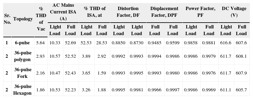
Comparison of Simulated Power Quality Parameters of the DTCIMD Fed from Different AC–DC Converters.
| Sr. No. | Topology | % THD of Vac | AC Mains Current ISA (A) | % THD of ISA, at | Distortion Factor, DF | Displacement Factor, DPF | Power Factor, PF | DC Voltage (V) | ||||||
|---|---|---|---|---|---|---|---|---|---|---|---|---|---|---|
| Light Load | Full Load | Light Load | Full Load | Light Load | Light Load | Full Load | Full Load | Light Load | Full Load | Light Load | Full Load | |||
| 1 | 6-pulse | 5.64 | 10.33 | 52.69 | 52.53 | 28.53 | 0.8850 | 0.8730 | 0.9485 | 0.9599 | 0.9858 | 0.9881 | 616.6 | 607.6 |
| 2 | 36-pulse polygon | 2.93 | 10.57 | 52.52 | 3.89 | 2.92 | 0.9992 | 0.9993 | 0.9994 | 0.9986 | 0.9986 | 0.9979 | 611.7 | 608.1 |
| 2 | 36-pulse Fork | 2.16 | 10.47 | 52.43 | 3.65 | 1.59 | 0.9993 | 0.9995 | 0.9993 | 0.9980 | 0.9986 | 0.9976 | 611.7 | 607.9 |
| 2 | 36-pulse Hexagon | 1.86 | 10.53 | 52.23 | 3.26 | 1.88 | 0.9995 | 0.9981 | 0.9966 | 0.9997 | 0.9986 | 0.9969 | 611.1 | 605.7 |
Table I lists the power quality indices obtained from the simulation results of the 6-pulse and 36-pulse converters. Fig. 7 depicts two groups of nine-phase voltage waveforms with a phase shift of 10 degrees between the same voltages of each group. The voltage across the interphase transformer (shown in Fig. 8) has a frequency equal to 9 times that of the supply which results in a significant reduction in volume and cost of magnetics. The 36-pulse converter output voltage (shown in Fig. 9) is almost smooth and free of ripples and its average value is 605.7 volts which is approximately equal to the DC link voltage of a six-pulse rectifier (607.6 volts). This makes the 36-pulse converter suitable for retrofit applications. Input current waveforms and its harmonic spectrum of the 6-pulseand 36-pulse converters extracted and shown in Figs. 10–17, respectively to check their consistency with the limitations of the IEEE standard 519. These harmonic spectrums are obtained when induction motor operates under light load (20% of full load) and full load conditions.


.")
.")
Obviously, for 6-pulse converter, fifth and seventh order harmonics are dominant. Hence, input current THD of this converter will be relatively a large amount and is equal to 28.53% and 52.53% for full load and light load conditions that are not within the standard margins. It is observed from the results that the THD of ac mains current at light load (20%) in Topology Polygon is 3.82, shown in Fig. 12, and that at full load is 2.92%, as shown in Fig. 13. Similarly, Fig. 14 shows the THD of ac mains current at light load in Topology Fork as 3.47% and at full load as 1.59%, shown in Fig. 15.
.")
.")
.")
.")
On the other hand, as shown in Figs. 16–17, Hexagon connected 36-pulse converter has an acceptable current THD (3.26% for light load and 1.88% for full load conditions). In this configuration, low order harmonics up to 33rd are eliminated in the supply current. In general, the largely improved performance of the 36-pulse converter makes the power quality indices such as THD of supply current and voltage (THDi and THDv), displacement power factor (DPF), distortion factor (DF), and power factor (PF) satisfactory for different loading conditions.
.")
.")
The aforementioned criteria are listed in Table I for the three types of converters. The converter in Topology Polygon, Fork, and Hexagon needs magnetics of 124.84%, 132.54%, and 106.35% of the drive rating respectively. The Delta/Hexagon connected platform could simplify the resulted configuration for the converters and reducing the costs. It can be observed that the TUF for Delta/Hexagon connected 36-pulse AC–DC converter is 89.46% which is better than the Delta/Polygon and Delta/Fork connected transformers used for 36-pulse AC-DC converter.
5ConclusionThis paper presents the design and analysis of a transformer based 36-pulse ac–dc converters which supplies direct torque controlled induction motor drives (DTCIMD's) in order to have better power quality conditions at the point of common coupling. The 36-pulse converter output voltage is accomplished via two paralleled eighteen-pulse ac–dc converters each of them consisting of nine-phase diode bridge rectifier. Afterwards, the proposed design procedure was modified for retrofit applications. Simulation results prove that, for the 36-pulse topology, input current distortion factor is in a good agreement with IEEE 519 requirements. Current THD is less than 4% for varying loads. It was also observed that the input power factor is close to unity resulting in reduced input current for DTCIMD load. Thus, the 36-pulse ac–dc converter can easily replace the existing 6-pulse converter without much alteration in the existing system layout and equipment. The Delta/Hexagon connected platform could simplify the resulted configuration for the converters and reducing the costs. The Delta/Hexagon scheme has an optimized configuration in this regard. The Delta/Hexagon design method will be suitable even when the transformer output voltages vary while keeping its 36-pulse operation.
Motor and Controller Specifications:
Three-phase squirrel cage induction motor—50 hp (37.3kW), three phase, four pole, Y-connected, 460 V, 60 Hz. Rs=0.0148 Ω Rr=0.0092 Ω; Xls=1.140; Xlr=1.14 Ω, XLm=3.94 Ω, J=3.1Kg • m2.
Controller parameters: PI controller Kp=300; Ki=2000. DC link parameters: Ld=2 mH; Cd=3200 μF. Source impedance: Zs=j0.1884 Ω (=3%).