


The sustainability criterion in the manufacturing industries is imperative, especially in the automobile industries. Currently, efforts are being made by the industries to mitigate CO2 emission by the total vehicle weight optimization, machine utilization and resource efficiency. In lieu of this, it is important to understudy the manufacturing machines adopted in the automobile industries. One of such machine is the hot stamping machine that is used for about 35% of the manufacturing operations within the automobile industries. Therefore, the standardization and optimization of the hot stamping process could reduce the carbon footprint within the automobile industries. This work understudied the on-delay timer functional valve of the hot stamping machine in order to determine various process parameters affecting it. The detailed physical model of the pneumatic and electro-pneumatic cylinder systems for the control is simulated and optimized for both the pneumatic and electro-pneumatic cylinder systems. Experimental and simulation model were established at the FESTO work station and FESTO FluidSIM® 5.1 respectively to evaluate the effective velocity, accelerations, displacement, and flow rate for the pneumatic and electro-pneumatic actuator on both systems. Comparisons were made between pneumatic and electro-pneumatic cylinder systems on their characteristic curve in order to optimize the process variables. The result favours the electro-pneumatic cylinder systems in stability and in designing hot stamping machines. The result obtained could elucidate the understanding of the pressing arm of a hot stamping machine.
It was proposed that CO2 can be mitigated with the production of lighter weight vehicles to reduce fuel consumption, and reduce CO2 emissions to the atmosphere (Hagenah, Merklein, Lechner, Schaub, & Lutz, 2015; Li, Chiang, Tseng, & Tsai, 2014a; Li et al., 2014b). Hot stamping technology is one of the key ways to optimize energy demand within the automobile manufacturing industry (Oldenburg, Steinhoff, & Prakash, 2008, 2009; Oldenburg et al., 2009; Karbasian & Tekkaya, 2010). Hot stamping is a method that was used in applying gold tooling in book printing in the 19th century (Cambras, 2004). Hot stamping was officially documented in Germany by Ernst (Benedek, 2005) in 1892 as the printing method used on leather and paper materials. Hot stamping has also been adopted for making plastics and printing of security cards since 1950s (Karbasian & Tekkaya, 2010; Wang & Lee, 2013). Hot stamping can be defined as a dry printing process of lithographic material in which foil or dry paint of different colours are being superimposed on a surface at high temperatures (Benedek, 2005). This is commonly applicable within the plastic, paper and security industries. It has a minimal pollution effect on the environment. The exploitation of hot stamping machine (HSM) in automotive body structure manufacturing is growing yearly. Some automobile companies use more than 35% hot stamped parts for their models in the recent years (Karbasian & Tekkaya, 2010; Wang & Lee, 2013). Globally, there has been an increasing trend and rapid development and technological innovation in the production of pneumatically and electro-pneumatically operated machines (Gamal, Sadek, Rizk, & Abou-elSaoud, 2016). This is also visible within the technological development of HSMs. Some HSMs makes use of compressed air to produce their stamping effect (Harper, 2005). As the compressed air is passed to their systems, the cylinder expands to initiate the machines’ operations. During hot stamping operation, a heated die of higher temperature is mounted on the cylinder head and the product to stamp is placed on a table vice beneath the stamping head (Sugimoto, Sakai, Umemoto, Shimizu, & Ozawa, 2004). The printing is done by forcing the hot die on the work piece. This creates an impression on the surface of the product by the dry paint or foil dies (Benedek, 2005). Dies can be made of silicone rubber or metal to have a hard surface for an inscription; it can be cast directly or by stamping; and it carries high levels of details embossed on the surface of both the regular and irregular shapes to form a specific blueprint. Foils has multilayered coatings that transfer the blueprint to the surface of the product (Couchman, 1998). There are metallic and non-metallic foils, which consist of a release layer, a colour layer and an adhesive base. In metallic foils, the colour layer is replaced with a chrome or a vacuum-metallic aluminium layer. Foil dies are available in different metal shades e.g. copper, bronze, silver and gold. Different HSMs can be used for different purposes, but the most common HSMs are the simple up-and-down presses, which this research work is based on (Benedek, 2005; Couchman, 1998; Gamal et al., 2016).
1.1Hot stamping machines model advantage and system descriptionRecently, Trajkovic, Milosavljevic, Tunestål, and Johansson (2006) investigated diverse types of valves and relays (i.e. electromagnetic, electro-hydraulic, hydraulic, pneumatic, and electro-pneumatic actuators) for different machines. They reported on the challenges between fast response valves, relay and low flow rate. It was particularly interesting that pneumatic operated valve is more efficient and fit for the investigated HSM applications (Adeoye, Aderoba, & Oladapo, 2017; Watson & Wakeman, 2005). The electro-pneumatic and electro-hydraulic actuators have the same working principles except the difference in their resultant force generation and working media (Abdel-Hamid, Sohair, & Ahmed, 2015; Minh, Tjahjowidodo, Ramon, & Van, 2009; Ruan, Burton, & Ukrainetz, 2002). The pneumatic actuators have faster response time when compared with the hydraulic actuators. This is due to the low density of air adopted by the pneumatic actuators as its operating medium (Abdel-Hamid et al., 2015; Oladapo, Balogun, Afolabi, Azeez, & Asanta, 2015; Minh et al., 2009). Apparently, due to the compressibility of air and its nonlinear behaviour, the control system of pneumatic actuators tends to be difficult in terms of operation ability (Minh et al., 2009). The HSMs are operated on the principles of high temperature and high-pressure air as an energy source. The electro-pneumatic valves (EPV) and time relay valves can be improved options to electro-hydraulic or hydraulic system of operation. In order to decrease the inconsistency between the outward moving force prediction and the experimental measurement, investigations have been carried out extensively on the precision of the proposed model that evaluated pneumatic and automated electro-pneumatic designs (Minh et al., 2009; Mohamed & Shima, 2015; Oladapo et al., 2016). Stamping or pressing is the process whereby flat material is inserted in the form of a coil that passes through the die into a stamping press to form the desired shape of the material (Davis & Caldwell, 2006; Kalpakjian & Schmid, 2001). The HSM has temperature ranges between 40°C and 400°C, input voltage of 220V and a 600W heating capacity. The HSM heating capacity has a time delay control valve range of 0.1s–10s. The maximum stroke of the hot plate is 80mm from the reference point and a maximum pressure of 60bar on a one horsepower air compressor. The HSM can contain a hot plate of 140mm×170mm at a time. The time delay valve can be a normally close and/or a normally open valve. A normally close time delay valve has a lock adjusting screw that serves as the valve timer. The valve is designed to meet the flow rate requirements. It is a combinational of a 3/2-way valve, an air reservoir and a throttle relief valve. The 3/2-way valve can be of normally open or normally close position. The type adopted in this work is the normally open time delay valve. The normally open and normally close time delay valves are normally designed to be actuated for a period between 0 and 30s. This can be extended beyond 30s with additional reservoir. During the hot stamping operation, the pilot of the 3/2-way valve is actuated when the air reservoir pressure is about 12bar (Tokashiki, Fujita, Kagawa, & Pan, 1996).
1.2Aim and objectivesThe aim of this work is to understudy the functional valve of the HSM and to determine the parameters for its optimum performance. The specified objectives are to:
- 1.
Understudy the pneumatically and electro-pneumatically operated HSM with a view to proposing definite conclusions for its design and operations.
- 2.
Configure and simulate the HSM 3/2 way valve normally open spring return. The spring return is designed with a throttle valve to form a time delay valve with three outlets as shown in Figure 1 (a) and (c).
- 3.
Simulate the HSM time delay valve with two outlets as shown in Figure 1(d) in order to regulate the time of the forward and return stroke.
- 4.
Simulate the HSM relay with switch-on delay for the time delay of the electro-pneumatic system.
 Functional time delay valve with three outlets, (b) time delay valve with two outlets, (c) schematic representation of a time delay valve, (d) symbol of a time delay valve.")
The set up of the electro-pneumatic drive with FluidSIM® system is as shown in Figure 2. A schematic diagram of the electro-pneumatic control system (EPCS) was adopted to check the status of the stamp speed, delay time and smooth movement of the cylinder.
2Mathematical modelling of pneumatic system
In order to evaluate the performance of the air in the cylinder and the pneumatic behaviour, the mathematical analysis of the air, the cylinder and the piston must be examined. Air is known to be an incompressible multi component fluid, which composed of dry air and water vapour in thermal equilibrium. The pressure, velocity, area of the cylinder and piston and the flow rate of the double-acting cylinder is shown in Figure 3. The following assumptions are consider in the equation:
- •
The air flow is steady state and laminar.
- •
The gravitational force on the air is negligible.
- •
Area of the connecting tube is constant in linearity.
- •
The tempera ion of the system is kept constant.

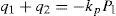
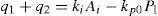
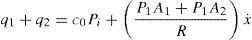
The general model for continuous flow of the system linearity of the flow rate of air is given by the following equations:
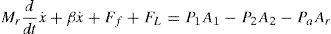
where a1=P1A1/RTs; a2=P2A2/RTs; q1, q2 and q3 represent the flow rate through each of the valves; x is controlling piston position; V1 and V2 are volumes of the double acting cylinder; P1 and P2 are the input and output pressures applied respectively to the system and Ai is the cross-sectional area of the double acting cylinder shown in Figure 3. The dynamic equation of motion of the piston-rod is described as:where, MP is the mass of the piston, x is the piston position at a particular point in time, β is the coefficient of viscous friction, Ff is the Coulomb friction force, FL is the external force from the stamp, P1 and P2 are the absolute pressures in the cylinder, PA is the absolute pressure. A1 and A2 – the piston effective areas, Ar– the rod cross sectional area.
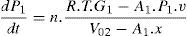
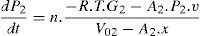
Few researchers for example (Beater, 2007; Ilyukhin & Arfikyan, 2011; Richer & Hurmuzlu, 2000; Takosoglu & Laski, 2011; Tokashiki et al., 1996) proposed the mathematical model used to analyze the electro-pneumatic control systems actuating a double acting cylinder for HSMs. In their models, the time delay 5/2 pneumatic valve with double air pilot was simulated and controlled by the computer and workstation for both the forward and the backward strokes. The models are based on four differential equations which describe the dynamics of the pneumatic cylinder pressures and specify the progressive movement of the mechanical control system, shown in Eq. (4). The equations consider the direction of the flow through the throttle valve.
where v is the speed of the piston, R is the universal gas constant, T is the working temperature of the compressed air; n is coefficient; F is the force on the output of the cylinder used to calculate the acting force on the piston.2.1Developed model equation

From Eq. (1) substituting the value of a1 and a2, and if the temperature is kept constant, then the model equation is as shown in Eq. (9).
If all the parameters of the system are taken into consideration. Where A1=0.00031415m2, A2=0.0002638m2, x=0.1m and R is the specific dry air constant=287.05Jkg−1K−1. The working input pressures are P1=5.05bar and P2=0.0bar deduced from the result in Figures 7 and 8. Thus, when there is an input pressure there is no output pressure and vice visa.
Therefore substituting all parameters, the general model for continuous flow of the system is given by Eq. (10).
3Experimental set-up
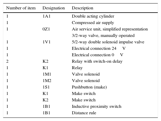
The component part of the HSM system mechanism is as shown in Tables 1 and 2 for the EPCS and PCS respectively. This consists of: 1) pneumatic double acting cylinders, which act as the mechanical stamping piston; 2) 5/2-way solenoid impulse valve pneumatically/electrically piloted with a manual override; 3) the supplying element that consists of the compressed air supply and air service unit; 4) the push button switch that closes at the actuation of the system and opens immediately after released; 5) the relay, which immediately switch on when current is passed and switch off immediately current is removed from the circuit; 6) the magnetic proximity switches which serve as the work piece in the experimental setup; 7) the relay, with switch-on delay that determines the time delay of the piston movement and 8) the valve solenoid that switches on the 5/2-way solenoid impulse valve.
Description part list for EPCS.
| Number of item | Designation | Description |
|---|---|---|
| 1 | 1A1 | Double acting cylinder |
| 1 | Compressed air supply | |
| 1 | 0Z1 | Air service unit, simplified representation |
| 3/2-way valve, manually operated | ||
| 1 | 1V1 | 5/2-way double solenoid impulse valve |
| 1 | Electrical connection 24V | |
| 1 | Electrical connection 0V | |
| 2 | K2 | Relay with switch-on delay |
| 1 | K1 | Relay |
| 1 | 1M1 | Valve solenoid |
| 1 | 1M2 | Valve solenoid |
| 1 | 1S1 | Pushbutton (make) |
| 1 | K1 | Make switch |
| 1 | K2 | Make switch |
| 1 | 1B1 | Inductive proximity switch |
| 1 | 1B1 | Distance rule |
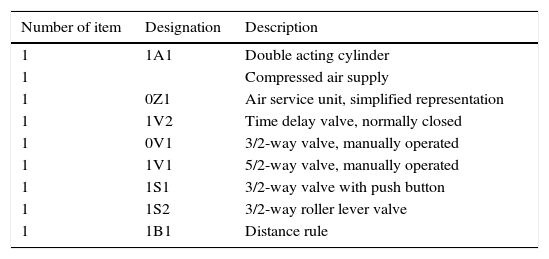
Description part list for PCS.
| Number of item | Designation | Description |
|---|---|---|
| 1 | 1A1 | Double acting cylinder |
| 1 | Compressed air supply | |
| 1 | 0Z1 | Air service unit, simplified representation |
| 1 | 1V2 | Time delay valve, normally closed |
| 1 | 0V1 | 3/2-way valve, manually operated |
| 1 | 1V1 | 5/2-way valve, manually operated |
| 1 | 1S1 | 3/2-way valve with push button |
| 1 | 1S2 | 3/2-way roller lever valve |
| 1 | 1B1 | Distance rule |
The arrangement of the component parts that made up the HSM system mechanism that is created to behave like the HSM for the EPCS and PCS are as shown in Figures 4 and 5 respectively. From Figures 4 and 5, it can be seen that the parts are systematically arranged to depict the sequential and logic flow of the HSM process.


The stamping control system was also designed with the pneumatic FluidSIM® software as shown in Figure 6. From Figure 6, the cylinder head is actuated with a forward stroke by depressing the pushbutton 1B1 as shown in Figure 6 in the pneumatic circuit. It sends signals to the 5/2-way impulse pneumatically double piloted valve controller 1V1 and open the inflow of high-pressure air coming directly from the compressor. The double acting cylinder is being actuated by a combined signal sent from the 3/2 roller lever valve, normally close and the 5/2-way valve. The air flows from the compressor through the 3/2 roller valve to the time delay normally open functional valve. This causes the cylinder to move forward and backward after a specified time.

The description and the designation of each part of the component in Figures 3 and 6 are itemized in Tables 1 and 2. The flow rate of the system that reaches the double acting cylinder is determined by the flow rate of the compressor, the air service systems and the opening level of the time delay valve. The 5/2-way impulse double pneumatically piloted valve and the longitudinal slide valve have five ports and two positions. This is used as a final control element that links the valves to the double acting cylinder and to the 3/2-way valve with normally closed pushbutton with a spring return. The control valve has three port and a manually operated switch for actuation. A mechanically piloted spring return 3/2-way roller lever valve is used to activate the movement of the double acting cylinder. The normally closed time delay valve is made up of a pneumatically operated air piloted 3/2-way valve, a one-way flow control valve (throttle valve) and an air accumulator that regulates the time delay of the air inflow. The FESTO FluidSIM® software is adopted to simulate the HSM control system. The developed FESTO FluidSIM® consist of: the normally close time delay valve DSNU-20-100-PPV-A, the 5/2 single pilot configured to a single piloted spring return normally closed 3/2 valve D:TP-BG-VL-S/2-Q4, a throttle valve D:TP-PPV-GRLA for opening the compressed air, the time adjustment valve D: TP-BG-PZVT-3/2G-3OS-Q4 used to acquire the experimental data, the metre rule for distance measurement, an air service with an air filter that regulates the airflow states designated D: TP-PVV-LFR-MICFQ and the piston adopted which is designated DSNU-20-100-PPV-A as shown in Figures 4 and 5. The piston rod, piston diameter and the stroke length of the rod cylinder were 8mm, 20mm, and 100mm respectively. A linear scale of 200mm long, measured the displacement of the cylinder before and after excitation. The air pressure is measured with a 10bar pressure gauge. The experiments were carried out under a maximum pressure of 6.0bar for safety and in order not to exceed the operating pressure of the HSM (Fig. 7).
4Results and discussions The simulation diagram result of dependence of position and velocity on time of pneumatic system 5% opening of time delay valve. (B) The simulation diagram result of dependence of position and velocity on time of pneumatic system 75% opening of time delay valve.")
Different computer simulations and experimental process ware carried out by means of the developed model shown in Figures 8 and 9. The following results were obtained to ascertain the workability of the system. First, in the process of the HSM, speed movement of the FESTO FluidSIM® platforms was observed. The positioning distance, velocity and acceleration of the actuator (the actuator is the main stamping arms of the cylinder where the stamping, pad is attached to aid the processes) that is used for the stamping arm of the machine were controlled. As the process progresses and as the pressure level of the compressor reaches 6bar, it was observed that there was a fluctuation on the movement of the pressure dropping lower than the 6bar before increasing further up to the 6bar mark after about 0.06s of operation. This phenomenon was noticed on the pressure gauges for both pneumatic and electro-pneumatic experimental value. The simulated analysis also exhibited the drop and high-pressure differences as shown in Figure 8 but no significant difference in the result obtained. From the analysis of the actuator. The magnetic cushion of the double acting cylinder help to reduce the sudden initial kick-off of the system from within the time frame of 0.4s. This aid the slow down movement of the actuator in order to have good and stable impression without the application of an impulsive force which could create a dent and a default impression on the workpiece. It has been proposed in the literature (Li et al., 2014a; Li et al., 2014b; Oldenburg et al., 2008, 2009) that a force exerted by a pressure of 6bar is enough to create an impression on the workpiece when heated.
 Simulation result of electro-pneumatic system 2s relay with switch on-delay. (B) simulation result of electro-pneumatic system 0.5s relay with switch on-delay. The time delay for alloy material should be different from non-alloy material. From Figs. 7–9 it can be seen that the relay switch was only activated at the return stroke of the cylinder for all the test carry out which means it is the part of component that activate the return stroke. The inductive proximity switch shows the position of the cylinder at a point in time.")
(A) Simulation result of electro-pneumatic system 2s relay with switch on-delay. (B) simulation result of electro-pneumatic system 0.5s relay with switch on-delay.
The time delay for alloy material should be different from non-alloy material. From Figs. 7–9 it can be seen that the relay switch was only activated at the return stroke of the cylinder for all the test carry out which means it is the part of component that activate the return stroke. The inductive proximity switch shows the position of the cylinder at a point in time.
 Experimental result of dependence of position and velocity on time of pneumatic system 75% opening of time delay valve. (C) Experimental result of electro-pneumatic system 2s relay to switch on-delay (D) Experimental result of electro-pneumatic system 0.5s relay to switch on-delay.")
The experimental result of dependence of position and velocity on time of pneumatic system 5% opening of time delay valve. (B) Experimental result of dependence of position and velocity on time of pneumatic system 75% opening of time delay valve. (C) Experimental result of electro-pneumatic system 2s relay to switch on-delay (D) Experimental result of electro-pneumatic system 0.5s relay to switch on-delay.
At the point of actuation there was a flow of air from the supply unit through the air service station to the control valve for 5/2-way solenoid impulse valve and 5/2-way impulse double pneumatically piloted valve for electro-pneumatic and pneumatic system respectively as shown in Figure 7. Air is then supplied with a 3/2 roller lever valve which served as the workpiece in the system and the on-delay timer valve that controls the time of movement of the piston. From Figure 5, on the electro-pneumatic system, the electric signal is passed from the 22 v.
5ConclusionsThe electro-pneumatic and pneumatic system for the hot stamping machine is presented in this paper. The on-delay timer valve was designed, developed and configured on the FESTO didactic workbench in order to mimic and simulate the HSM pneumatic system for sustainable performance. The simulated HSM was built using the main HSM components. The experimental and simulation results show the characteristics and behaviour of the air movement within the system. This result is also a proof that the delay time of the system can be obtained more precisely and accurately with the on-delay timer valve incorporated in the assembly as shown by the simulation and experimental analyses conducted in this work. This is helpful to advance the performance and optimization of the HSM. The following conclusion can further be drawn from this work:
- •
It can be observed that the possibility of magnetic cushion system at the two ends of the adopted standard pneumatic cylinders prevented the sudden stamping of the work piece. Hence, to avoid increase in scrap and/or rework rate due to sudden stamping in HSM, it is proposed that magnetic cushion system be incorporated into the HSM. This system can provide the required shocks absorber during the HSM's stamping operations.
- •
Although, It can be deduced from both the simulations and experimental set up that the pneumatic operated system for on-delay timing is unpredictable, the HSM can be operated with both the pneumatic and electro-pneumatic system variables depending on the workpiece material. The workpiece material determines the amount of force to be exerted during a stamping operation.
- •
It is also clear that the cycle time varies depending on the in-flow of air from the supply element. Hence for sustainability and process optimization, it is proposed that the HSM be controlled with a 24V input electrical energy under specified time duration for the delay time on the workpieces since the 24V input supply on the electro-pneumatic operated HSM helps to reduce the electrical energy consumption when HSM is incorporated with electro-pneumatic and pneumatic system. This could further create an awareness on the electrical energy consumption of the industrial based HSM in order to improve the resource waste and increase the economic objective for the HSM usage.
- •
The reduction in the consumption of electrical energy with the proposed 24V for PCS and EPCS could further reduce the emission of CO2 to the environment which in turn reduces carbon footprint of the Hot Stamping Machine operations.
The authors have no conflicts of interest to declare.
Peer Review under the responsibility of Universidad Nacional Autónoma de México.