


In this article authors present an application of spatial processing methods for GPS spoofing detection and mitigation. In the first part of this article, a spoofing detection method, based on phase delay measurements, is proposed. Accuracy and precision of phase delay estimation is assessed for various qualities of received signal. Spoofing detection thresholds are determined. Efficiency of this method is evaluated in terms of probability of false alarm and probability of detection when 4 to 8 GPS signals are received. It is shown that the probability of spoofing detection is greater than 99 percent if carrier-to-noise ratio is at least 46dBHz. The second part of the article presents a GPS spoofing mitigation method which uses spatial filtering (null-steering) for excision of undesired signals. Performance of this method is analyzed in various conditions. Attenuation of undesired signals is estimated to be at least 60dB when their signal-to- noise ratio is high. Furthermore, statistical analysis of the spatial filtering influence on the availability of true signals is provided. Eventually, a concept of practical anti-spoofing system implementation is proposed.
Global Positioning System receivers are present in many devices, starting from chips installed in simple trackers and smartphones [1], through professional geodetic devices, to high-dynamics receivers used in aviation and space vehicles. Apart from it, GPS is used to provide accurate synchronization to telecommunication networks and power grids. For a large number of these applications integrity of GPS signals and correctness of navigation data is critical, in order to compute accurate position, velocity and time (PVT) information. However, it must be remembered that GPS signals may be easily jammed even by signals of power equal to several Watts, depending on the distance from jammer [2].
GPS spoofing is a more sophisticated technique than jamming, since in this case the interference imitates the true navigation signals arriving from GPS satellites. Without any protective features, a GPS receiver is vulnerable to spoofing. The signals emitted by spoofer (spoofing device) not only jam the true signals but also cause the estimation of incorrect PVT values. Advanced receivers perform the Receiver Autonomous Integrity Monitoring (RAIM) algorithm. However, if the parameters and navigation data of spoofing signals comply with the current orbital parameters, RAIM may not detect the lack of integrity. It is especially probable in scenarios when spoofer initially simulates the true position of receiver and gradually deviates it to the wrong one.
It is clear that additional features are required to detect and mitigate GPS spoofing. Many methods of spoofing detection are proposed [3], such as:
- –
detecting unusual values or changes of power-related parameters: carrier-to-noise density ratio, absolute received signal power, power variations, L1/L2 band power ratio,
- –
monitoring time-related parameters: length of interval between phase transitions, delay between signals transmitted on different frequencies,
- –
- –
spatial processing – detecting multiple signals with the same direction of arrival using a multi-antenna receiver or a mobile single-antenna receiver,
- –
cryptographic protection,
- –
using hybrid navigation systems (GNSS+INS) [4], and many others. Nevertheless each of them has some drawbacks, concerning either increased complexity and cost or effectiveness limited to a certain set of spoofing scenarios. For example, one of suggested methods is based on checking whether the received signals are modulated with military P(Y) code, which is usually absent in spoofing signals [5]. Despite being effective, this solution uses two receivers and requires that one of them is protected from spoofing, which is not always possible.
In general, effectiveness of spoofing detection methods depends on the sophistication level of spoofer. For example, carrier-to-noise density detection algorithms may be defeated through adding an artificial white noise and changing the relative instantaneous amplitudes of fake signals.
The most sophisticated spoofers adjust the PRN code phase and carrier phase to match those of true signals arriving to a target receiver [6]. The usage of such device is limited, since it requires the knowledge of precise distance between the spoofer and the attacked receiver. While it may seem to be possible in certain situations, then using multiple scattered antennas to transmit synchronized signals, in order to imitate spatial separation of satellites, is very unlikely. This is the reason why the spoofing detection methods based on spatial processing are highly robust. The relative directions of arrival of signals from different space vehicles (SVs) are likely to be the most reliable factors during distinction between genuine and fake GPS signals. The undisputed advantage of such solutions is the inherent direction of arrival (DoA) estimation, results of which may be used to filter out the spoofing signal through beamforming or null steering.
To restore the correct operation of a spoofed GPS receiver, spoofing mitigation procedures are applied. Various approaches to solve this problem may be found in the literature [3]. Vestigial Signal Detection method, used for spoofing mitigation, subtracts the local code and carrier replicas from buffered samples of composite received signal and then repeats the acquisition in order to detect and acquire suppressed signals from GPS satellites. When using this method, an assumption is made that the power of false signal is significantly higher than the power of true signal. It may not be fulfilled when the receiver is far from the spoofer. In such case, the true signals may be discarded in favor of the ones used for spoofing. Moreover, if spoofer's signals have considerably higher power than desired signals, the latter may not be detected, due to quantization error.
Another countermeasure, Receiver Autonomous Integrity Monitoring (RAIM), compares pseudorange measurements and discards the outliers resulting from presence of false signals. This approach may fail in scenarios, where spoofer is synchronized with true signals or when all the true signals are jammed, making it impossible to compare the measurements.
The most robust methods of GPS spoofing detection and mitigation seems to be the ones which use spatial processing. The necessity of antenna array usage results in increased complexity of the receiver, but it may be acceptable when robustness is the main criterion.
Spatial processing methods which use multiple antennas for reception of GNSS signals have already been proposed in various approaches in the last few years [7], [8]. Their applications are mostly related to jamming and interference mitigation. However, the performance of these spatial algorithms in various conditions is usually insufficiently investigated. In subsequent chapters of this article authors present an example solution which applies the antenna array processing for GPS spoofing detection and mitigation. Effectiveness of this method is also assessed.
2Spatial processingThere are various ways of obtaining the direction of arrival or angle of arrival estimate. They include: mechanically or electronically controlledreception pattern antennas, phase interferometry, subspace-based methods such as MUSIC or ESPRIT and others. Most of these possibilities require additional signal processing blocks. In GNSS receivers available on the market, signal processing blocks are usually integrated into one chip without any external access to samples of received signals. That is why the best way to assess the performance of DoA estimation is to use a software receiver with an analog front-end. Off-the-shelf chip-scale GPS front ends are available, yet they usually provide only one or two bit output sample resolution, which is sufficient for GPS signal reception, but it may be too low for DoA application. It is better to use a separate preamplifier and an analog down converter followed by a high-resolution multi-channel digitizer.
Subspace-based methods of DoA estimation are computationally efficient and accurate, however they require relatively high Signal-to-Noise Ratio, which is not the case of GPS signals hidden almost 20dB below noise floor. Nevertheless, they may be applied to the post-correlation signals [9]. The other approach, selected by authors of this article, is to measure the received signals' phase shifts which may be used to estimate theDoA through phase interferometry.
Direction of arrival corresponds to the phase delay differences of signals at the outputs of receiving antenna array elements. The level of ambiguity in resolving DoA is highly dependent on array geometry and characteristics of array elements (sensors).
Since spoofing signals are practically always radiated from a single source, they arrive to the receiver from the same direction, no matter if it is a line-of-sight or a reflected signal. On the other hand, genuine signals from GPS satellites arrive from different directions within the whole hemisphere, assuming the clear view of the sky. Basing on this assumption, GPS spoofing is detected when multiple received signals have the same or very similar DoAs.
Azimuth and elevation, which represent two-dimensional DOAs, are non-linear functions of phase delays. That is why a relation between the phase delay estimation error and the DoA estimation error depends on relative orientation between source of signal and receiving antenna. Thus for GPS spoofing detection it is more reliable to compare the phase delays than to compare the actual DoAs.
3Simulation modelIn this paragraph the model of received GPS signals as well as the model of the antenna array are described. They are necessary assumptions to assess the performance of proposed counter-spoofing methods.
3.1Signal modelIn order to determine the effectiveness of proposed spoofing detection method, a simulation model was developed. This model assumes that transmitted signals are only subject to the additive white Gaussian noise (AWGN) and their delays are proportional to the distances between the source of signal and particular elements of the antenna array.
Signals received by multiple antenna elements may be described as follows:
where i=1,&,M is the array element number, Pi is the received power of i-th signal, ti is the total delay of transmission from the signal source to thei-th element, c is the pseudorandom C/A code sequence, d is the navigation message data sequence, fc is carrier frequency and ni is the additive noise at i-th element.
One of the antenna array elements is selected to be the reference. Only the signals received through this element pass the full signal processing path of GPS receiver, that is acquisition and tracking phase, including C/A code phase and carrier phase estimation. Acquisition procedure, as well as code and carrier tracking loops are implemented in software, according to algorithms presented in [10]. The remaining blocks of GPS receiver, i.e. pseudorange estimation, navigation message decoding etc. are not involved in spoofing detection procedure.
Signals from the rest of the outputs of antenna array are correlated with the same local replica which is used for correlation with the reference signal. Since the relative delays between signals are less than one L1 carrier period, which is over 1500 times shorter than duration of one C/A code chip, the code phases of corresponding signals at all antenna elements are practically the same.
Multiplying the received signal with a C/A code replica provides the carrier modulated with navigation data. The next operation is correlation with complex carrier which provides the information about the phase shift:
where Zi is the complex sample at correlator output. Phase of carrier replica is adjusted to match the phase of the reference signal from the first sensor. Thus, the rest of computed phase shifts are the DoA-related phase delays between the first and the other array elements.3.2Antenna array model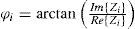
While selecting an antenna array configuration for DoA estimation, many factors have to be taken into consideration. First, the number of sensors. Two sensors may be used for phase delay discrimination [7] and for limited estimation of the angle of arrival. However, when using such an array, the same phase shifts are possible for baseline-symmetrical azimuths. Adding the third non-in-line element to the array eliminates the ambiguity of the azimuth. Even more elements are necessary for unambiguous two-dimensional DoA estimation. On the other hand the number of sensors must not be too high. There are limitations on the size of the antenna array. When the distance between sensors is larger than half of the wavelength, phase ambiguity occurs. A large number of closely-spaced sensors increases mutual coupling. Also more signal processing paths are required in this case, which increases hardware and computational complexity.
Besides the number of elements, their arrangement is important. The most popular are planar arrangements: uniform linear/rectangular array (ULA, URA) [11], as well as circular array or circular array with additional central sensor. Non- planar arrays may be beneficial for 2D DoA estimation [12].
Four-sensor uniform circular array was selected for purpose of described simulation research. Configuration of elements is presented in Fig. 1. Spacing d between neighboring elements is equal to 0.45 wavelength. It is less than half wavelength in order to decrease the level of phase ambiguity when the noisy signal impinges on the array from direction parallel to any of the array's baselines.

As all of the elements are located on a plane which is parallel to the ground, there exists an uncertainty whether the elevation is positive or negative. However, in case of GPS antennas, signals are received only from directions with positive elevations, so estimated elevation angles may be mapped to range from 0 to 90 degrees.
Coupling between sensors, which depends on specific types of antenna elements, is not taken into consideration in this model. It may have a significant influence on amplitude and phase of received signals, thus should be investigated in practical implementations.
4Simulation resultsPreliminary performance assessment of the described spoofing detection and mitigation methods was made basing on the results of the following simulations.
4.1Mean and RMS value of phase delay estimation errorA series of simulations were conducted in order to assess the accuracy and precision of phase delay estimation with various signal-to-noise ratios. In each scenario two parameters were measured for phase delays: mean value offset and root-mean-square error (RMSE).
Since the power spectral density of GPS signals is below the noise floor and all the signals share the same frequency band, it is difficult to estimate the wideband SNR value. In this case, carrier to noise density ratio (C/N0) is used to assess the received signal quality. It is calculated after correlation, when the pseudorandom C/A code and the navigation data are removed from carrier. The relation between signal-to-noise ratio and C/N0 in civilian GPS is:
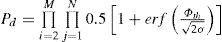
where B is the GPS C/A signal bandwidth equal to 2.046MHz. Simulations were performed for C/N0 from 35dBHz to 60dBHz, as it is a range of values mostly occurring during reception of real GPS signals. Four uncorrelated realizations of AWGN were added to relatively delayed GPS waveforms to obtain desired SNR. To check whether it is the only source of signal distortion, C/N0 was estimated using three different procedures described in [13],[14]: Variance Summing method, Beaulieu's method and Moments method. For each method, the difference between theoretical and measured value in range from 40dBHz to 60dBHz was less than 0.5dB. Measured C/N0 error values are presented in Fig. 2.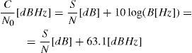

Phase delay measurements are calculated after correlation with 1ms integration time. They are contained in-π to π range by default. If the nominal phase delays are close to the borders of this range, phase wrapping may cause the increase in RMS error and mean value offset. That is why the computed phase delays are additionally mapped into −2π to 0 and 0 to 2π ranges. For each pair of array elements the range with the lowest variance within last 100ms is selected to provide the samples used to assess accuracy and precision.
The charts presenting mean value offset and RMS error as a function of C/N0 are shown in Figs. 3 and 4 respectively. For each C/N0 value, 10 iterations were executed and the average value was taken. In each iteration 5 seconds of signal were analyzed. Simulations were conducted for various directions of arrival and each time the results were very similar, which means that phase delay error is independentfrom nominal phase delay.


As may be seen, the offset of mean value oscillates around zero value in entire C/N0 range. It proves that AWGN does not decrease the accuracy of phase estimation.
The RMS error is the same for all three pairs of array elements. Eq. 4 describes the least squares approximation of RMSEφ as a function of C/N0.
4.2Phase delay error distribution
Distribution of phase delay difference error must be known in order to evaluate the probability of spoofing detection, as well as the probability of false alarm. Statistical analysis was conducted on the samples of phase delay error to decide whether it follows a normal distribution. A sample histogram of phase delay estimation error is presented in Fig. 5. As may be seen, it resembles the Gaussian bell curve. However, to make sure that it is in fact normal, another two tests were carried out.
.")
First, the obtained phase delay estimation error values were plotted on a normal test plot. The distribution is assumed to be normal, if the samples coincide with the diagonal line. As may be seen in Fig. 6, the coincidence is very good.

Another test was the calculation of the Anderson-Darling statistic in order to numerically assess the goodness of fit. For significance level α=0.05, it is said that the distribution is normal if the statistic value is less than 0.752. Calculations were done for integer values of C/N0 in range from 40dBHz to 60dBHz. The results are shown in Fig. 7. All of the values do not exceed the threshold, so it may be assumed that the phase delay error is distributed normally.
4.3Probability of spoofing detection
In ideal conditions, all spoofing signals would cause the same phase delays. In the noisy channel they are not exactly the same. Presence of spoofing might be detected by checking whether the phase delay differences of multiple GPS signals are below the specific threshold. Knowledge about possible phase delay error is important for selection of such threshold levels which would maximize the probability of detection.
Incorrect GPS spoofing detection, called false alarm, may occur in situations when multiple true satellite signals are received from similar directions and all phase delay differences are below predefined threshold. In order to determine how large these differences may be, the positions of all GPS satellites within 24 hours period were computed with 1 minute interval. For each time interval, a number (from four to eight) of visible satellites, with most similar directions of arrival, were selected and nominal values of phase delay differences were calculated. Assuming that probability of false alarm Pfa is not greater than 10−4, threshold level ϕth may be evaluated from:
where ϕij is the j-th difference of phase delays between first and i-th element of antenna array, N=(K−1)K/2 and K is the considered number of spoofing signals (fake satellites).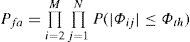
If phase delays are normal random variables with variance σ2≈RMSEφ2, then:
where ϕij0 are the true differences of phase delays, i.e. without error caused by noise.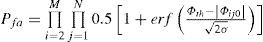
Threshold levels were calculated for C/N0 range from 35dBHz to 60dBHz. Receiving antenna positions were set to 0, 15, 30, 45, 60, 75, 90 degrees north and 0 degrees of longitude, according to WGS84 coordinates. Final threshold level was selected for each case as the minimum from values obtained for different positions of the receiver. Results, for various numbers of satellites involved in spoofing, are shown in Fig. 8.

After determination of the detection thresholds, probability of spoofing detection Pd was estimated using expression similar to Eq. 6:
Probabilities of detection, as functions of C/N0 and number of satellites, are presented in Fig. 9. For C/N0 greater than 47dBHz practically every presence of spoofing will be detected, irrespective to the number of fake satellites. To provide at least 99% probability of detection with 4 to 8 satellites, carrier-to-noise ratio must not be less than 46, 41 and 39, 38 and 36dBHz respectively.
4.4Performance of null-steering for spoofing mitigation
After information about relative phase delays of spoofing signal is obtained, null-steering is applied to suppress all the signals arriving from particular direction. The optimum complex weight vector w for null-steering using M-element antenna array is:
where Δφ1,m is the unwanted signal phase delay between the first (reference) and m-th element of array [16]. Filtering process is performed according to the following expression: where sfilt(t) is the antenna array output signal and sm(t) is the signal received through m-th sensor of array.

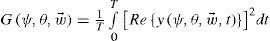
Complex signal y(t) at the output of proposed antenna array may evaluated using Eq, 10, assuming unitary power of arriving signal:
where ψ is the DoA azimuth angle, θ is the DoA elevation angle, φc(t) is carrier phase at reference sensor, wm is the m-th element of weight vector, d1,m is distance between first and m-th array element and λ is wavelength. Elements of array are assumed to be isotropic. Array gain is calculated in the following way: where T is equal to one carrier period.

Pattern described by Eq. 12 refers to the signal component located exactly at L1 frequency. Since the dimensions of antenna array are related to a particular wavelength, the attenuation varies for different frequency components of received signals. In addition, this variation is a function of DoA. For example, if elevation angle is equal to 90°, all relative phase delays are zero and high attenuation is constant in whole frequency range. Largest differences of attenuation occur for low elevation angles and azimuth angles close to 0° and 180°. Fig. 10. shows the example frequency characteristics of the selected array in 2.046MHz band around L1 frequency, at 0° DoA azimuth. As may be seen, center frequency component is completely eliminated from output signal. Attenuation on the borders of analyzed frequency range is much lower. Assuming that spectrum of noisy spoofer's signal is flat, total attenuation GGPS in 2.046MHz band, at 0° elevation of arrival and 0° or 180° azimuth of arrival, is equal to about −60dB.

Phase estimation error causes changes in shape of antenna array reception pattern. Erroneous phase delays are not connected with specific DoA, so the pattern does not have a distinct null. In other words, presence of noise and interference decreases the attenuation of all signals arriving from the direction of spoofing source. To constrain a null in direction close to DoA of spoofing signal, the best-fit DoA is calculated for inaccurate phase delays. Error function is selected to be the mean- square difference of phase delays:
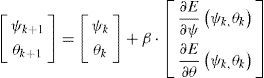
where Δφ(ψ,θ) is a phase delay connected with specific DoA while Δφ* is the phase delay estimated in presence of noise. Gradient optimization is used to evaluate the best-fit DoA. It involves an iterative procedure which may be described in the following way: where k is iteration index and β is a real constant coefficient which affects the convergence of the procedure and the number of iterations required to achieve acceptable error value. Initial null direction is set to {ψ0,θ0}=[0°, 45°]. Eventually, new set of phase delays is calculated, based on resulting DoA. These phase delays, instead of those primarily estimated, are used to form the array weight vector as in Eq. 8. Average attenuation of spoofing signals, arriving from 0 azimuth and 0 elevation, before and after optimization of weight vectors, is presented in Fig. 11. Results, for each C/N0 value, were obtained by averaging 1000 attenuation values calculated for normally distributed random phase delays. It may be seen that the optimization significantly increases the attenuation of undesired signals. As C/N0 increases, attenuation approaches the –60dB value, which is the limit for signals impinging on array of proposed configuration from mentioned DoA. On the other hand, if no optimization is performed, the attenuation of spoofing signals is not satisfactory, especially for low C/N0.4.5Influence of null-steering on reception of true GPS signals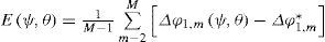

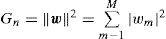
Null-steering towards source of spoofing signal results not only in excision of this unwanted signal, but may also have negative influence on quality of desired, true signals, arriving from GPS satellites. A ttenuation of satellite signals may be estimated from Eq. 10, considering wide bandwidth. Relative noise power between input and output of the array must be also taken into account to calculate changes in signal-to-noise ratio caused by spatial filtering. Since the ambient noise does not have a one specific source in space, its attenuation Gn depends only on the weights vector and is expressed in the following way:
Simulation research was conducted to estimate the probability that SNR decrease exceeds acceptable level for given number of visible satellites. This level depends on expected SNR in receiver's location without spoofing activity. Positions of all operating satellites were computed, basing on GPS almanac, within 24-hour period with 1 minute interval. GPS receiver's positions were set to 0°, 15°, 30°, 45°, 60°, 75° and 90° North, 0° of longitude with 0m height, according to WGS-84 coordinates. DoAs and corresponding changes of SNR were computed for all of satellites' and receiver's positions. DoAs of spoofer's signals, represented by pairs of azimuth and elevation angles, were selected respectively in ranges from 0° to 360° and from 0° to 90°, with 5° step. For each of analyzed acceptable SNR decrease levels, a cumulative distribution function (CDF) was calculated as the minimum of CDFs estimated for all receiver's positions. Resultant probability distribution was evaluated through differentiation of this CDF. Statistical representation of obtained results is shown in Fig. 12. If 12dB SNR decreaseis acceptable, full satellite visibility is most likely. On the other hand, when quality of true signals is poor and only 3dB SNR decrease is tolerated, number of excised signals is larger, with 2 being the most probable value. From practical point of view, information about the number of signals possible to receive is more important than about the absolute number of excised signals, since the total number of visible satellites varies with time and receiver's position. Thus, another investigation was performed in order to evaluate the probabilities that certain number of satellite signals are possible to be received when null-steering is enabled. Results of this analysis are presented in Fig. 13. Probability that at least 4 satellites are visible is over 95 %, if acceptable SNR decrease is less than −1dB. To provide over 95 % probability of at least 5, 6 and 7 visible satellites ΔSNR thresholds must be set to –2dB, −4 dB and −7dB, respectively.
5Concept of the anti-spoofing system

In order to verify the results obtained from simulations, a proof-of-concept of the proposed anti-spoofing system is going to be implemented. The general concept is presented in Fig. 14.

Signals from the outputs of a four-element antenna array are amplified and downconverted from RF to IF in an analogue front-end which also performs automatic gain control. IF signals at 2.5MHz are sampled in the data acquisition board installed in a high-end PC. The following stages of signal processing are performed in dedicated software. Amplified and bandpass filtered RF signals are transmitted form the front end to a null-steering board which consists of four signal paths, eachincluding a wideband phase shifter and a voltage controlled attenuator. Values of attenuation and phase shift are set according to spoofing signals phase delays estimated in software. Next, the signal which is a sum of four phase shifted component signals is provided to a commercial GPS receiver, so that the result of spoofing mitigation may be assessed.
The functions which are realized in software are depicted in form of a block diagram in Fig. 15. First, four signals which are sampled in DAQ board with 8.192MHz sampling frequency are written to a long buffer in random access memory. This buffer can contain 60 seconds of signal and after that period the oldest data are replaced with currently acquired samples. The samples from buffer may be written to a file as a reference signal for post-processing. Next, GPS signals acquisition procedure is realized based on samples acquired in the first signal path. Acquisition function returns the number of received signals, satellite identification numbers, coarse carrier Doppler shifts and C/A code phase shifts. These parameters, along with signal samples, are passed to GPS signal tracking loop, which follows the changes of Doppler frequency and phase of C/A code. Carrier phase is also estimated so the coherent carrier replica may be generated locally.

Carrier phase shifts in the second, third and fourth signal paths are estimated through multiplication of samples with this replica and C/A code. Next step is the calculation of phase delays between the signals from the first and the other signal paths. After that, differences of respective phase delays are calculated for all of the visible satellites. Spoofing detection procedure is executed basing on these data. If all of the phase delay differences are below the threshold, it is decided that multiple signals arrive from the same direction, which means that spoofing is present.
In case of spoofing detection, estimated phase delays are passed to the null-steering board which filters out the unwanted signals. In addition, software null steering may be performed using the same phase delays. The samples of filtered signals are stored in a file for post-processing. Samples of signals before and after null-steering may be fed to a software GPS receiver in order to verify the effectiveness of spoofing mitigation.
The presented block diagrams describe a new concept which is currently being practically implemented.
6ConclusionGPS spoofing is a serious threat and, in fact, it is not very difficult to realize such an attack. It is clear that robust countermeasures, composed of detection and mitigation algorithms, are required.
Spatial signal processing, which takes advantage of multi-antenna reception is one of the most effective ways of distinguishing between true and fake GPS signals.
Results of simulations presented in this article show that comparison of phase delays may be used for GPS spoofing detection. It provides low probability of false alarm and high probability of detection, unless only four signals with low signal-to-noise ratios are received.
Additive white Gaussian noise was assumed in simulation as the only interference with received GPS signals. Other types of disturbance, such as narrowband signals or selective fading are spread during correlation and result in raised noise spectral density. Probability of detection in presence of interference of any type may be estimated if C/N0 is known.
There is a possibility to extend the presented method of spoofing detection to create a combined detection and mitigation solution. Estimated phase delays of spoofing signals may be used to calculate complex weight vector. This vector shapes the antenna array pattern in a way that a null is pointed towards source of spoofing signal, without rejecting true signals from satellites.
This article proves that spatial filtering may be used as a robust way of GPS spoofing mitigation. Proposed optimization of array weights provides high attenuation of undesired signals. Furthermore, large probability of at least four useful satellite visibility is sustained, unless their nominal signal-to-noise ratio is low in receiver's location. Spatial processing is also beneficial, as it may be successfully used in combined spoofing detection and mitigation solution. It is also worth mentioning that proposed approach does not require any additional information about the antenna's attitude, since the reference frame is array-fixed.
During this research authors assumed that false signals arrive only from one direction at a time. Some additional investigations should be done to evaluate the performance of proposed methods in a multipath environment, where replicas of undesired signals may arrive from different directions.