


Lamina and laminate mechanical properties of materials suitable for flywheel high-speed energy storage were investigated. Low density, low modulus and high strength composite material properties were implemented for the constant stress portion of the flywheel while higher density, higher modulus and strength were implemented for the constant thickness portion of the flywheel. Design and stress analysis were used to determine the maximum energy densities and shape factors for the flywheel. Analytical studies along with the use of the CADEC-online software were used to evaluate the lamina and laminate properties. This study found that a hybrid composite of M46J/epoxy–T1000G/epoxy for the flywheel exhibits a higher energy density when compared to known existing flywheel hybrid composite materials such as boron/epoxy–graphite/epoxy. Results from this study will contribute to further development of the flywheel that has recently re-emerged as a promising application for energy storage due to significant improvements in composite materials and technology.
extension, extension-bending, bending stiffnesses respectively
Young's modulus
lamina strength
shape factor
kinetic energy
force resultant; number of lamina
moment resultant
laminate strength
energy density
axial thickness of flywheel
integration constant; curvature
mass
number of sequence repetition
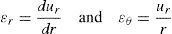
radius
displacement
strain
LAMINA lay-up
Poisson's ratio
stress
density
angular velocity
fiber direction
disk and rim respectively; outer position of disk and rim respectively
center of flywheel
cylindrical coordinate directions
tensile and compressive
Cartesian coordinates directions
In-plane
Energy storage technologies are becoming practical solutions for situations where energy is required to be saved for use at a different time. Today, viable energy storage technologies include flywheels and batteries. The flywheel has recently re-emerged as a promising application for energy storage due to significant improvements in materials and technology. When compared to conventional energy storage systems, the flywheel has many advantages which include high power/energy density, much less environmental problems, availability of output energy directly in mechanical form and high efficiency. Composite materials flywheel allow for much higher density than conventional steel-based flywheels due to their lower density and potentially higher tensile strength.
One of the first studies which showed that composite materials with significantly large specific strength are well suited for flywheel energy storage applications was Rabenhorst (1971). Aspects of the report on comparison of flywheel material properties indicated that the use of 70% graphite whisker/epoxy material for the flywheel leads to a factor of 17.6 improvement over maraging steel that was considered to be the highest strength isotropic material for a constant stress flywheel rotor. DeTeresa and Groves (2001) examined the performance of commercial high-performance reinforcement fibers for application to flywheel power supplies and concluded that carbon fibers are preferred for highest performance. Dems and Turant (2009) presented methods for the design of reinforced composite flywheels for maximum kinetic energy while Tzeng, Emerson, and Moy (2006) studied elastic and viscoelastic behavior of composite flywheels and proposed methodology, material characterization and test matrices for the design in order to achieve maximum performance. Clerk (1964) pointed out that a major requirement is the need to significantly increase the energy density and Janse, Petrus, Groenwold, and Wood (2013) studied some composite flywheel rotor design methods and proposed a formulation for improvement toward achieving high energy density.
Wen and Jiang (2012) reported on maximizing the energy storage capacity of a hybrid composite multi-ring flywheel. Results show that the composed rings of the hybrid flywheel rotor can nearly reach the limits of strength in both radial and circumferential directions. Ha, Kim, Nasir, and Han (2012) studied different rim design cases of hybrid composite flywheel rotor based on strength ratio optimization. The rotor was composed of four composite rims made of carbon-glass/epoxy with hoop wound reinforcements of varying volume fractions. Alexandrova and Vila Real (2009) designed composite flywheel based on the model of annular rotating disk with stress-free boundary condition while thin rim or multi-trim flywheel was reported by Post and Post (1973) where individual thin rings basically in pure uniaxial stress circumferentially were made to spin about a common axis. Wang, He, Zhao, and Li (2012) studied a multilayer rim carbon fiber/glass fiber, composite flywheel for ultimate strength requirement. Results show that selecting the layer thickness and hybrid ratio of carbon fiber to glass fiber can reduce radial strength requirement of the rim material.
Studies (Bolund, Bernhoff, & Leijon, 2007; Chang & Hirschfeld, 1978; Genta, 1985; Kirk, 1977) have found that possible flywheel shapes for energy storage include the constant stress disk, conical disk, constant thickness (pierced and unpierced) disk, disk with rim and thin rim. Metwalli, Shawki, and Sharobeam (1983) designed configurations that maximize the energy density of variable material flywheels and proposed an optimum design of a constant stress flywheel whose material density varies radially. One of the conclusions reached in the study is that a multi-element alloy flywheel will provide a higher inertia per unit mass than a flywheel made of one element with a higher specific strength. Georgian (1989) reported on the optimum design of composite flywheel consisting of inner disk of low density, high strength and low modulus of elasticity composite material and an outer disk of constant thickness with high density, high strength and high modulus of elasticity. The results show that maximum energy density was achieved using a combination boron/epoxy for the rim and high strength graphite/epoxy for the constant stress portion of the flywheel leading to the conclusion that in order to obtain high energy densities, a search for a higher strength and lower density composite for the disk is required. This present study investigated composite materials with low densities, low modulus and high strength for the constant stress portion and a higher density, higher modulus and strength for the constant thickness portion. Analytical studies along with the use of the CADEC-online software were used to evaluate the lamina and laminate properties.
2Flywheel stress analysisFigure 1 shows the views of the flywheel used in the study. It is a constant stress disk and a constant thickness rim flywheel with an angular velocity of ω rad/s. The sectioned annular element at a radius, r, is in equilibrium under the action of the forces shown.

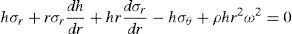
The equilibrium and compatibility equations can be shown respectively to be (Stodola, 1945):
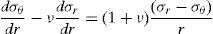
The strain–stress relations of an isotropic material are given as:
and the strain–displacement relations are given as: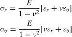
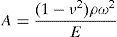
Substituting (4) in (3) and then in (1) simplifies to give
where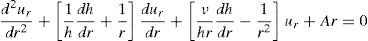
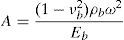
Consideration of the constant stress disk makes (1) to become
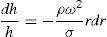
Integrating (6) and noting that at r=ra, h=ha gives
where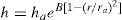

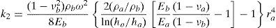
It is noted that for the rim, h=ha=constant. Substitution of this in (5) gives
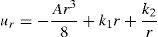
whose solution can be shown to bewhere k1 and k2 are integration constants.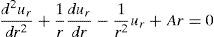
Using the expression for ur in (4) and the relations in (3) gives
Georgian (1989) showed that the constant stress portion of the flywheel becomes bulgy for large values of ln(ho/ha). Thus, the center cannot carry its share of the rim load. Hence the limit of ln(ho/ha) for maximum energy density is approximately equal to 2. Figure 2 shows the profile of the constant stress disk flywheel used in this study. Based on the results of previous studies, the disk and rim are made of different composite materials with indicated elastic properties.

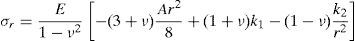
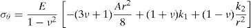
The stress distribution in the disk portion is given as
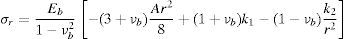
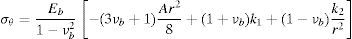
while the stress distribution in the rim is given as:where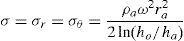
The integration constants, k1 and k2 are obtained using the following boundary condition at the interface between the disk and rim, that is, at r=ra.
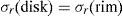
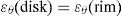
Using the above boundary conditions, it can be shown that:
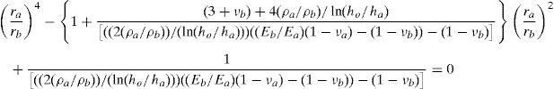
and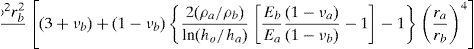
Eq. (17) gives the radii ratio (ra/rb). It is a ratio that gives the optimum radial dimensions of the flywheel.
These dimensions satisfy the boundary conditions.
It should be noted that the stress analyses is for a flywheel with different materials for the constant stress portion and constant thickness rim taking into consideration the differences in the Poisson's ratios of the materials.
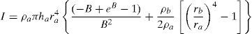
3Energy density of the flywheelUseful parameters for assessing flywheel systems include the energy density of the rotor and its associated shape factor, K. It can be shown that the energy density of the rotor at burst speed is dependent only on the flywheel design and on the characteristics of the material. As shown in Genta (1985) and other studies, the energy density is given as:
where e is the energy density, KE is the kinetic energy of the flywheel and m is the mass of the flywheel. σ and ρ are the tensile strength and density of the rotor material respectively.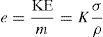
The mass and mass moment of inertia can be shown to be respectively as
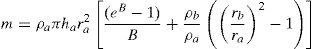
From (18), (19) and (20) it can be shown that the shape factor of the disk is given by:
where B is defined as4Composite material properties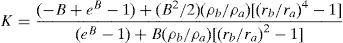

The above analyses are for isotropic materials. Though the bending behavior of a quasi-isotropic laminate is not quite the same as an isotropic plate, a properly designed symmetric quasi-isotropic laminate can behave like an isotropic plate. The flywheel material for this study is assumed to be properly designed, symmetric and quasi-isotropic.
The classic plate theory is used in the analysis of laminates. It relates the force (N) and moment (M) resultants to the in-plain strains (¿0) and curvatures (κ). This can be expressed as
where the [ABD] matrix is obtained from the lamina properties. Many micromechanics models have been used to predict the properties of a composite lamina. As stated by Barbero (2011), the periodic microstructure micromechanics produces accurate predictions for all the moduli of a unidirectional lamina. This was used in the computation of the lamina properties.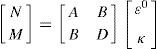
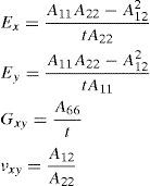
In a symmetric quasi-isotropic laminate the bending-extension stiffness matrix [B] are zero. According to Akkerman (2001), the in-plane stiffnesses are independent of the composite orientation. The general lamina layup in a quasi-isotropic laminate is given (Barbero, 2011; Akkerman, 2001) as
where k is the lamina number, N is the number of laminates (N≥3), and θo is an arbitrary reference angle. The practical quasi-isotropic laminate layups are [0/±60]nS and [0/±45/90]nS, n being the number of sequence repetition. In terms of the extensional stiffness matrix, the laminate in-plane moduli are given (Barbero, 2011) aswhile the laminate strength, using the maximum stress criterion, is given as:
A computer aided design environment for composite software (CADEC, 2011), developed by Barbero and available online, was used to evaluate the lamina and quasi-isotropic laminate elastic properties, using the periodic microstructure micromechanics for the lamina properties.
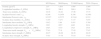
5Results and discussionTables 1–3 show properties of the fiber and matrix, lamina and laminates respectively for volume fraction of 0.7 and lamina thickness of 1.6mm. The laminate was designed with a 10% coefficient of variance for 95% reliability with respect to the first ply failure (FPF) using a reference load of 1000N/mm.
Fiber and matrix properties.
| Fiber–polyacrylonitrile (PAN) (Toray, 2008) | Matrix (Ashland, 2015) | ||||
|---|---|---|---|---|---|
| T1000G | M35J | M46J | T-650/35 | Epoxy (470-36S) | |
| Density, ρ [g/cm3] | 1.8 | 1.75 | 1.84 | 1.77 | 1.150 |
| Longitudinal modulus, E [GPa] | 294 | 343 | 436 | 255 | 3.6 |
| Poisson's ratio | 0.2 | 0.2 | 0.2 | 0.2 | 0.38 |
| Longitudinal tensile strength, Ft [MPa] | 6370 | 4700 | 4210 | 4280 | 90 |
Evaluated lamina properties with a volume fraction of 0.7.
| M35J/epoxy | M46J/epoxy | T1000G/epoxy | T650-35/epoxy | |
|---|---|---|---|---|
| Density [g/cm3] | 1.57 | 1.633 | 1.605 | 1.584 |
| Longitudinal modulus, E1 [GPa] | 241.2 | 306.3 | 206.9 | 179.6 |
| Transverse modulus, E2 [GPa] | 18.16 | 18.42 | 17.96 | 17.75 |
| In-plane Poisson's ratio, ν12 | 0.246 | 0.2459 | 0.246 | 0.2461 |
| Intralamina Poisson's ratio, ν23 | 0.5357 | 0.5375 | 0.5344 | 0.533 |
| In-plane shear modulus, G12 [GPa] | 7.195 | 7.271 | 7.137 | 7.075 |
| Intralamina shear modulus, G23 [GPa] | 5.912 | 5.99 | 5.851 | 5.789 |
| Longitudinal tensile strength, F1t [MPa] | 3305 | 2957 | 4482 | 3014 |
| Longitudinal compressive strength, F1c [MPa] | 1528 | 1533 | 1523 | 1518 |
| Transverse tensile strength, F2t=F2c [MPa] | 77.83 | 77.8 | 77.85 | 77.87 |
| Intralamina shear strength, F4 [MPa] | 28.27 | 28.26 | 28.28 | 28.29 |
| In-plane shear strength, F6 [MPa] | 77.81 | 77.79 | 77.83 | 77.85 |
Evaluated quasi-isotropic laminate [0/±45/90]S, properties.
| M35J/Epoxy | M46J/Epoxy | T1000G/epoxy | T650-35/epoxy | |
|---|---|---|---|---|
| Density [g/cm3] | 1.57 | 1.633 | 1.605 | 1.584 |
| Longitudinal modulus, E1 [GPa] | 92.21 | 114.1 | 80.66 | 71.44 |
| Transverse modulus, E2 [GPa] | 92.21 | 114.1 | 80.66 | 71.44 |
| Shear modulus, Gxy [GPa] | 35.04 | 43.23 | 30.71 | 27.25 |
| Poisson's ratio, νxy | 0.3157 | 0.319 | 0.3132 | 0.3107 |
| Ultimate strength, Ft [MPa] | 6323.75 | 5658.75 | 8577.50 | 5768.13 |
For validation purposes, the results from this study were compared to those from Georgian (1989) using ln(ho/ha)=2, rb=0.24m, ha=0.02m and the quasi-isotropic composites material properties.
The bolded results in Table 4 are from this study. As can be seen the two analyses are in close agreement.
Compared results of analyses.
| Constant thickness materialConstant stress material | (ra/rb) | Shape factor (K) | Energy density (kJ/kg) | |||
|---|---|---|---|---|---|---|
| Boron/epoxyGraphite/epoxy (High strength) | 0.8354 | 0.8357 | 0.9467 | 0.9462 | 97.723 | 97.673 |
| Boron/epoxyGraphite/epoxy (High modulus) | 0.8387 | 0.8380 | 0.9395 | 0.9409 | 58.592 | 58.683 |
As stated in Georgian (1989) conclusion, in order to obtain high energy density a search for a higher strength, lower modulus and lower density for the constant stress portion is required. In his study boron/epoxy–graphite/epoxy composites combination gave the highest energy density. Hence, the materials being investigated were compared to boron/epoxy–graphite/epoxy. Table 5 shows a combination of composites from Table 3 and the high strength boron/epoxy–graphite/epoxy. A factor of safety of 3 was used for the constant stress portion (disk) of the flywheel. As seen from the listed energy densities, the combination of M46J/epoxy and T1000G/epoxy gives the maximum energy density. It is about 18 times more than the boron/epoxy–graphite/epoxy. This is due to the current high modulus and high strength carbon fibers.
Different material combination for disk and rim of flywheel.
| Constant thickness materialConstant stress material | Shape factor (K) | Energy density (KJ/kg) |
|---|---|---|
| Boron/epoxyGraphite/epoxy | 0.9467 | 97.723 |
| M46J/epoxyM35J/epoxy | 0.9554 | 1282.8 |
| M46J/epoxyT1000G/epoxy | 0.9647 | 1718.5 |
| M46J/epoxyT650-35/epoxy | 0.9708 | 1178.3 |
Figure 3 shows the stress distribution of the flywheel for M46J/epoxy–T1000G/epoxy combination. The stress in the disk (constant stress portion) is 2859MPa. The tangential stress in the rim (the constant thickness portion) has a maximum value of about 3689MPa.

Previous published results have shown that in order to obtain higher energy densities, a search for a higher strength and lower density composite for the constant stress portion is required. This is clearly shown in this report. Properties of several composite materials suitable for flywheel energy storage were investigated. Design and stress analysis were used to determine for each material, the maximum energy densities and shape factor of the flywheel. The materials identified based on the results from this study outperformed the boron/epoxy–graphite/epoxy combination.
6ConclusionPrevious research results have shown that in order to obtain higher flywheel energy densities, a search for a higher strength and lower density composite for the constant stress portion is required. Elaboration on this was done in this study. Properties of several composite materials suitable for flywheel energy storage were investigated. Design and stress analysis were used to determine the maximum energy density and shape factor for the flywheel. The materials identified for this, based on the results from this study demonstrated outperformance compared to the boron/epoxy–graphite/epoxy combination. Results from this study will contribute to aiding further development of the flywheel that has recently re-emerged as a promising application for energy storage due to significant improvements in composite materials and technology.
Conflict of interestThe authors have no conflicts of interest to declare.
Peer Review under the responsibility of Universidad Nacional Autónoma de México.