


Ruthner powder is a by-product of the steel hot-rolling process. This study introduces a new application area for this waste material by investigating its activity for the oxygen evolution reaction. Ruthner powder with the α-Fe2O3 phase structure was deposited on the carbon paper substrates using the electrophoretic deposition (EPD) process to fabricate the electrodes. The effect of the concentration of cetrimonium bromide ([CTAB]) and the Ruthner powder ([RP]) in the EPD cell on the morphology and activity of the electrodes were investigated by SEM, LSV, and EIS techniques. The results revealed the formation of a homogenous layer on the carbon paper when [CTAB] and [RP] were respectively 0.4g.l−1 and 0.2g.l−1. The obtained electrode showed the best activity among all fabricated electrodes. In particular, its onset overpotential and overpotential at a current density of 10mA.cm−2 were respectively 85% and 25% lower than those of bare carbon electrodes.
El material en polvo «ruthner» es un subproducto del proceso de laminación en caliente del acero. El presente estudio introduce una nueva área de aplicación para este subproducto residual, al investigar su actividad en la reacción de evolución de oxígeno. Se depositó polvo ruthner con estructura cristalina α-Fe2O3 sobre sustratos de carbon paper utilizando el proceso de deposición electroforética (EPD) para la fabricación de electrodos. Se investigó el efecto de la concentración de bromuro de cetrimonio (CTAB) y el polvo ruthner (RP) en la celda de EPD sobre la morfología y la actividad de los electrodos, mediante técnicas SEM, LSV y EIS. Los resultados mostraron la formación de una capa homogénea sobre el carbon paper cuando (CTAB) y (RP) fueron respectivamente 0,4 g/L-1 y 0,2 g/L-1. El electrodo obtenido con dicha composición mostró la actividad más destacada entre todos los electrodos fabricados. En particular, su sobrepotencial y su sobrepotencial inicial, estudiados a una densidad de corriente de 10 mA/cm-2 fueron 85 y 25%, respectivamente, valores mucho más bajos que los del electrodo de carbón referencia.
The water splitting (WS) reaction is a process to convert the H2O molecule to hydrogen and oxygen gasses. The reaction is thermodynamically an uphill reaction that needed significant energy to produce hydrogen. This energy could be supplied directly from solar energy or electrical energy maintained from photovoltaic cells or other renewable energy sources [1]. The obtained hydrogen could be used as a clean source of energy replacement of fossil fuels without releasing carbon dioxide and other greenhouse gases that contributed to global warming, ozone depletion, and acidic rains. Like other electrochemical reactions, the WS consists of two anodic and cathodic half-reactions, namely oxygen evolution reaction (OER) and hydrogen evolution reaction (HER), respectively. Since the water oxidation reaction requires a large overpotential for multi-step transfer of four electrons, the OER has sluggish kinetics compared to HER [2]. The use of electrocatalysts in this reaction could decrease the required overpotential and activation energy. Platinum group metals (PGMs) and noble metallic oxides like IrO2 and RuO2 are traditionally known as effective catalysts to accelerate the WS process, but their use has diminished because of their unavailability and expensiveness [3]. Thus, various studies are conducted to search for low-cost alternatives to these materials.
Several waste materials have shown great potential in water splitting applications. For instance, copper electronics waste has been successfully applied as a suitable support for the electrolytic water-splitting reaction [4]. It has also been reported that waste-yeast biomass catalysts greatly enhance electrocatalytic hydrogen production [5]. Additionally, the carbon-based structure materials derived from waste plastics have shown significant HER electrocatalytic performance [6]. Iron-based waste materials also have a significant capability for water splitting reaction. Accordingly, iron nano-sheets from tin-plated steel showed the OER onset over-potential of that is much smaller than reported the bulk iron.
Finding a cost-efficient source of iron oxide compounds could be desirable for WS applications. Accordingly, Ruthner powder is a by-product of the acid recovery unit of steel rolling mills. This iron-based waste material is produced after the hot-rolling process, in which an oxide layer forms on the steel slab. This layer is usually removed by the acid rinsing process. The obtained spent pickle solution is recovered in the acid recycling unit by spraying the solution into a reactor at a temperature of 400 to 750°C (spray roasting process) [7]. In the reactor, iron chloride solution is converted to Fe2O3 powder in the presence of water vapor and oxygen at high temperatures according to the following reactions:
The obtained iron oxide, called Ruthner powder or red powder, is a brown or red hematite. This waste material is an iron-rich source with low impurities and is regarded as an important raw material in various industry sectors, such as the production of iron powder, ductile iron, low-carbon steel, cement clinker, colors, and pigments [8]. Ruthner powder has also exhibited good oxidation catalytic behavior for CO conversion to CO2[9,10]. Therefore, the good electrocatalytic behavior of hematite for OER makes the Ruthner powder a good candidate for water oxidation applications.
Among the iron compounds, hematite (Fe2O3) is a well-known catalyst for photoelectrochemical water splitting [11,12]. Additionally, the iron oxide compounds are known as efficient electrocatalysts for water oxidation in alkaline media [13–16]. Arumugam et al. [17] reported that the nanostructured Fe2O3 catalysts could be a prominent candidate for electrochemical water splitting reaction. Su et al. [18] also synthesized electrodes from iron oxide-based nanoparticles and found out that this electrode shows a Tafel slope of mV.dec−1 and good electrocatalytic stability. In another research, Samanta et al. [19] reported that Fe2O3 nano-clew electrocatalyst shows an acceptable activity with a low overpotential of 440mV at a current density of 10mA.cm−2. However, the relatively low electrical conductivity of Fe2O3 is a limitation for using it as catalysts for the electrochemical process [20]. The deposition of electrocatalyst on porous conductive substrates such as carbon paper has been introduced as an effective approach to improve the electrical conductivity of the electrocatalysts for OER [21,22].
The electrophoretic deposition (EPD) method has widely been used as a promising method for producing electrocatalytic electrodes that involve the adsorption of fine catalysts particles with a large specific area on a substrate. Many electrodes such as the nano-nickel decorated by graphene electrode [23], MoS2 QDs/NFs/FTO [24], FeOOH/Ni(OH)2 on Ni Foam [25], SrTiO on FTO [26] and Co3O4 nanoparticles on glassy carbon electrode [27] have so far been produced by EPD method for water splitting application. Accordingly, it was demonstrated that various parameters such as voltage, current density, powder concentration, and surfactant concentration in suspension are important in the film morphology and the electrocatalytic performance of the obtained electrode [28].
This research introduces Ruthner powder as a potential electrocatalyst for the water oxidation reaction. The electrocatalysts were fabricated by the deposition of Ruthner powder on the carbon paper surface using EPD. Accordingly, the effect of the cetrimonium bromide (CTAB) surfactant and Ruthner powder concentrations in the EPD cell on the morphology and the electrochemical performance of the fabricated electrocatalysts was studied.
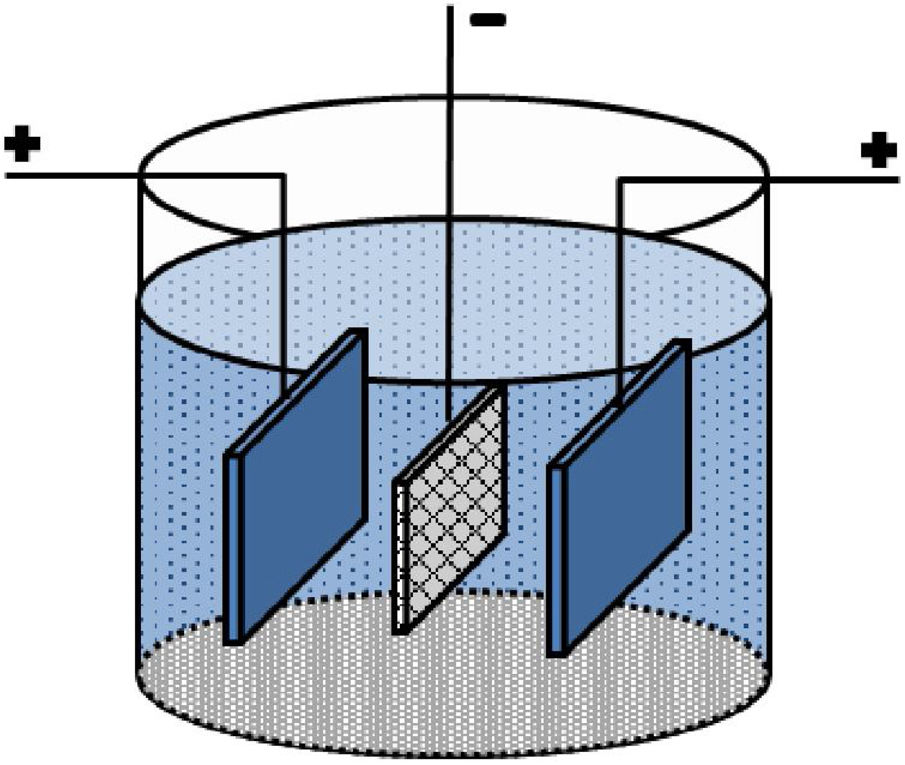
Experimental proceduresA carbon paper (SIGRACET, GDL 29) with a 1cm×1cm dimension was used as a conductive substrate with a high specific surface. Before EPD, the carbon paper substrates were ultrasonically cleaned by acetone for 10min. Fig. 1 shows a schematic of the employed EPD cell, where two stainless steel electrodes were used as the anode on both sides of a carbon paper (cathode electrode) [29,30]. Before each deposition, the stainless steels were carefully sanded, polished, washed with distilled water, and dried. The EPD was performed in deionized water using different concentrations of CTAB and Ruthner powder. The pH of the suspension was adjusted using hydrochloric acid (HCl). The EPD process parameters are listed in Table 1.

Electrophoretic process parameters.
| Parameters | Value |
|---|---|
| CTAB concentration (g.l−1) | 0.2, 0.4, 0.6, 1.0 |
| Particle concentration (g.l−1) | 0.05, 0.10, 0.20, 0.50 |
| Applied voltage (V) | 5 |
| Distance between electrodes (mm) | 10 |
| Electric field intensity (V.m−1) | 500 |
| Deposition time (s) | 300 |
| pH | ∼ 3 |
| Zeta potential* (mV) | +39.3 |
| Particle mobility* (cm2/V.s) | 3.06×10⁻⁴ |
| Conductivity* (mS.cm−1) | 0.311 |
| Viscosity* (mPa.s) | 0.891 |
In this research, the employed Ruthner powder was the by-product of the hot-rolling unit of Mobarakeh Steel Company (Isfahan, Iran). The phase structure of the Ruthner powder and a selected electrode was characterized by an X-ray diffractometer (XRD, Philips Expert, Germany) equipped with a copper Kα source (wavelength of 0.154nm). Transition Electron Microscopy (TEM, Philips CM200 FEG, Germany) was used to investigate the morphology and the size of Ruthner powder. Also, a Tescan MIRA3 scanning electron microscope was used to observe the morphology of the deposited layer on the substrate.
All electrochemical experiments were performed in a conventional three-electrode system in the 1M KOH solution (pH≈14) at room temperature, using the sample as the working electrode, a Pt sheet as the counter electrode, and a saturated calomel electrode (SCE) as the reference electrode. Before the electrochemical tests, the electrocatalyst was activated using 50 cyclic voltammetry scans at a scan rate of 100mV.s−1. Linear sweep voltammetry (LSV) measurements were conducted with a scan rate of 5mV.s−1. All potentials were converted from vs. SCE to the vs. RHE (reversible hydrogen electrode) by adding a value of 0.244+0.059 pH. All polarization curves were adjusted by applying iR compensation based on the resistance test. For electrochemical impedance spectroscopy (EIS) experiments, the frequency scans were carried out by applying sinusoidal wave perturbations of ±10mV in amplitude. The impedance values were recorded in a frequency range of 10kHz to 1Hz at the potential of 0.600V vs. SCE, at which all the electrocatalysts showed an appreciable electrocatalytic activity. The EIS spectra were analyzed by the Zview software.
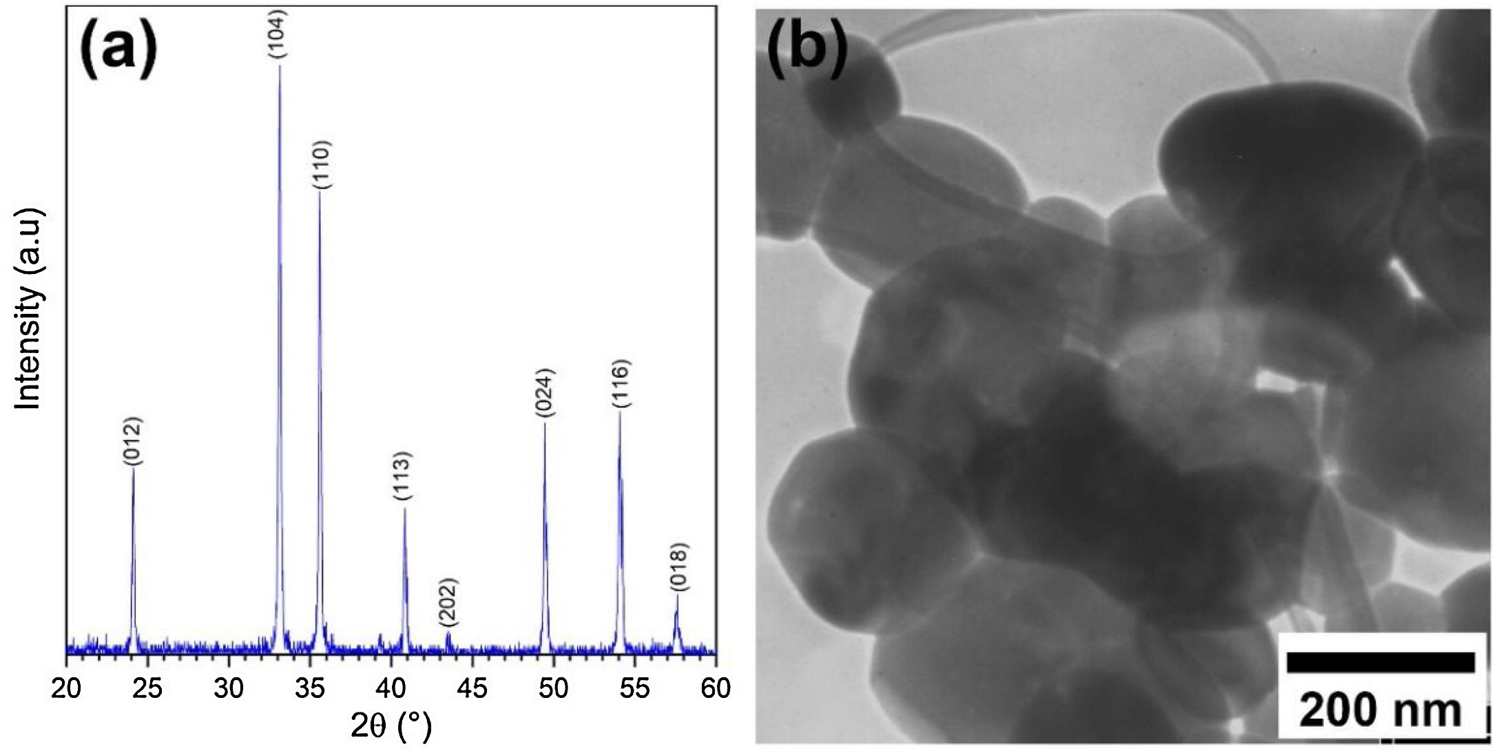
Results and discussionCharacterization of pristine Ruthner powderFig. 2(a) shows the XRD pattern of the employed Ruthner powder. As indexed, all the peaks in this pattern correspond to the different crystalline planes of the α-Fe2O3 phase (PDF 00-033-0664), indicating the high purity and crystallinity of the pristine Ruthner powder. The size of the crystallite of Ruthner powders was calculated to be ∼ 50 nm using Scherrer's equation [31]. The TEM image of the pristine Ruthner powder is shown in Fig. 2(b). TEM micrograph shows the powder consists of almost spherical particles in the size range of 50nm to 500nm.
Characterization of the deposited layer XRD pattern and (b) TEM image of the pristine Ruthner powder.")
Electrocatalytic electrodes were fabricated by the EPD process using different concentrations of CTAB ([CTAB]) and Ruthner powder ([RP]) in the EPD cell. In this work, CTAB is used as an effective cationic surfactant that charges the particles positively to be suitable for cathodic deposition. CTAB and SDS are regarded as the common surfactant for EPD of metallic oxide particles, increasing their zeta potential [32]. Ma et al. [33] have reported that the maximum zeta potential could be obtained for Fe2O3 suspension using CTAB surfactant when the pH of the suspension is in the range of 2.5–3.5.
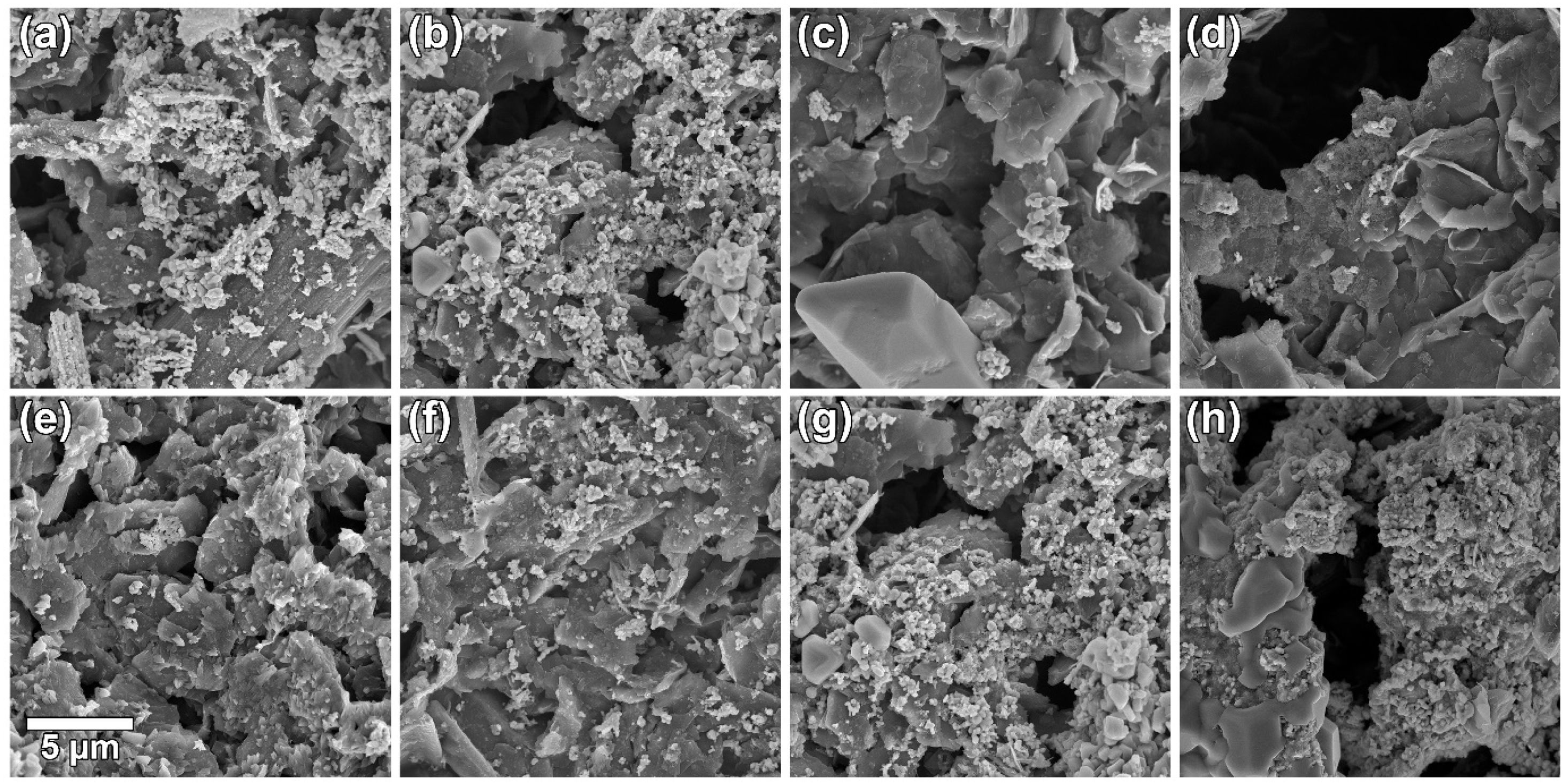
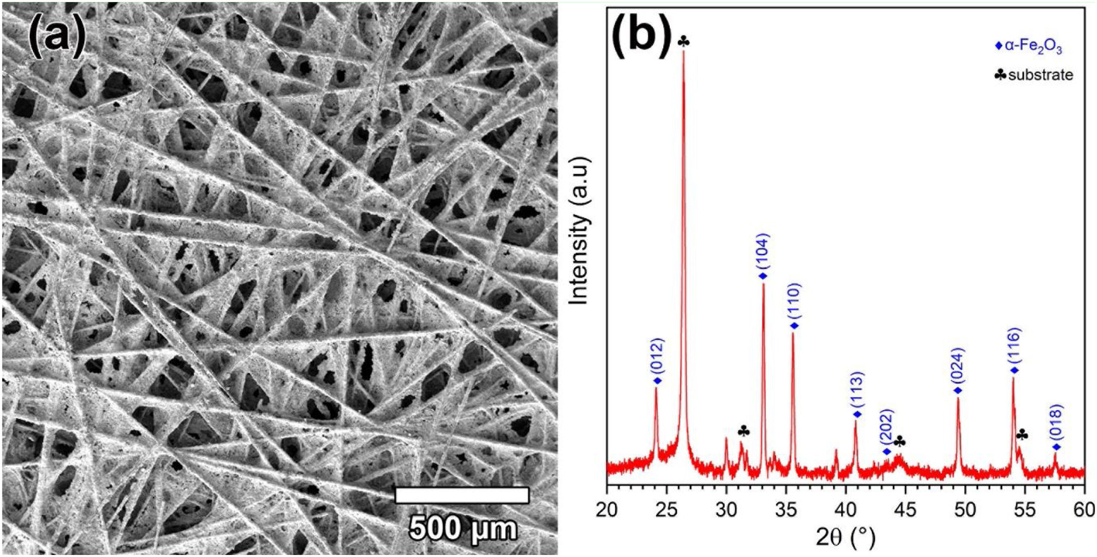
The effect of [CTAB] on the morphology of the deposited layer of Ruthner powder on the carbon paper substrate, when the [RP]=0.2g.l−1 is shown in Fig. 3(a–d). The results showed that increasing [CTAB] from 0.2g.l−1 to 0.4g.l−1 led to an increase in the amount of deposited Ruthner powder and provided a better distribution of Ruthner powder on the carbon paper substrate. However, further increasing [CTAB] to 0.6g.l−1 and 1.0g.l−1 resulted in a sharp decrease in the amount of deposited powder. Therefore, it seems that the 0.4g.l−1 is an optimum level for [CTAB] in this study. Fig. 4(a) shows a low magnification SEM micrograph from the surface morphology of the coating deposited at the optimum level of [CTAB], confirming that a homogenous layer of Ruthner powder fully covered the surface of the carbon substrate. The XRD pattern of the deposited layer is shown in Fig. 4(b). As expected, the peaks corresponding to the α-Fe2O3 phase and carbon paper substrate are detected in the structure.
![SEM micrographs of the surface morphology of electrocatalytic layers formed by EPD using: [CTAB] of (a) 0.2, (b) 0.4, (c) 0.6, and (d) 1g.l−1; [RP] of (e) 0.05, (f) 0.10, (g) 0.20, and (h) 0.50g.l−1.](https://static.elsevier.es/multimedia/03663175/0000006100000004/v1_202207290548/S0366317521000029/v1_202207290548/en/main.assets/gr3.jpeg?xkr=ue/ImdikoIMrsJoerZ+w997EogCnBdOOD93cPFbanNd3TCEZuNxhudow/+3Hrh9WJc+mtnYSSPL9K6mfMWVj1mF0vavFOcplWFUVrNl+WCuP2N/pFLhpdsv8fYsuW88fGJYzti/s8EMN3Mde5LUO1dNCnfQliRY/aNEGPJ2DMKJmeAiraUCs4Kurgz2Xm5GhLtdWZljFFUHpz6/FH2ypZAtjAL230UN1wu8WDH9H8I0gE5C1MVmo/uHiyxrW9elXgD5Fu2Q8dcB1Xs7lbICv54wdCkFAv3oDELEVmBxAm7Ujjyj/E3oQqVI5LoKTKrjG "SEM micrographs of the surface morphology of electrocatalytic layers formed by EPD using: [CTAB] of (a) 0.2, (b) 0.4, (c) 0.6, and (d) 1g.l−1; [RP] of (e) 0.05, (f) 0.10, (g) 0.20, and (h) 0.50g.l−1.")
![(a) Low magnification SEM micrographs of the surface morphology, (b) XRD pattern of electrocatalytic layers formed by EPD using [CTAB] 0.4g.l−1 and [RP] of 0.20g.l−1.](https://static.elsevier.es/multimedia/03663175/0000006100000004/v1_202207290548/S0366317521000029/v1_202207290548/en/main.assets/gr4.jpeg?xkr=ue/ImdikoIMrsJoerZ+w997EogCnBdOOD93cPFbanNd3TCEZuNxhudow/+3Hrh9WJc+mtnYSSPL9K6mfMWVj1mF0vavFOcplWFUVrNl+WCuP2N/pFLhpdsv8fYsuW88fGJYzti/s8EMN3Mde5LUO1dNCnfQliRY/aNEGPJ2DMKJmeAiraUCs4Kurgz2Xm5GhLtdWZljFFUHpz6/FH2ypZAtjAL230UN1wu8WDH9H8I0gE5C1MVmo/uHiyxrW9elXgD5Fu2Q8dcB1Xs7lbICv54wdCkFAv3oDELEVmBxAm7Ujjyj/E3oQqVI5LoKTKrjG "(a) Low magnification SEM micrographs of the surface morphology, (b) XRD pattern of electrocatalytic layers formed by EPD using [CTAB] 0.4g.l−1 and [RP] of 0.20g.l−1.")
The zeta potential is regarded as an important factor in the EPD, which can influence the deposited layer morphology [34], the direction and mobility of particles during the deposition process as well as the degree of stability of the suspension. The latter is attributed to the interaction between particles and the solution, where the suspensions with zeta potential higher than +30mV or lower than −30mV are highly stable [35]. Electrostatic and van der Waals forces are two main forces that have a significant effect on this interaction. During the EPD process, the attraction force between the particles increases as they approach each other, and hence a high electrostatic repulsion force is required to avoid agglomeration of particles. Increasing zeta potential could enhance the surface charge of the particles, and subsequently, provide further electrostatic repulsion forces between them. It can avoid particle agglomeration and increase the stability of the suspension, resulting in a more uniform layer with a better distribution of particles [36]. However, there is an optimum level for surfactant, and beyond this level, the addition of surfactant has a negative effect on the deposition process [37].
Fig. 3(e–h) depicts the effect of [RP] on the morphology of the deposited layer of Ruthner powder on the carbon paper when the [CATB] is kept constant at the optimum value of 0.4g.l−1. The bright features on the SEM images correspond to the deposited Ruthner powders, while the darker features are related to the carbon substrate. Depending on the EPD condition, a different distribution of Ruthner powder on the carbon substrate is observed. It can be seen that increasing [RP] in the EPD cell from 0.05g.l−1 to 0.50g.l−1 resulted in a gradual increase in the amount of deposited Ruthner powder. However, the electrode deposited at [RP]=0.50g.l−1 exhibited a different morphology than what was observed in the other electrodes, at which the Ruthner particles are agglomerated. Among all electrodes, the electrode deposited with [RP] of 0.20g.l−1 exhibited a highly uniform and well-distributed layer of Ruthner powder on the carbon paper substrate. In the EPD process, the concentration of particles in the solution is one of the important parameters that have a crucial role in the quality of sedimentation [36]. Accordingly, the value of 0.20g.l−1 is found to be the optimum level of the [RP] in the present study, and the layer deposited at the concentration beyond this level exhibited a non-uniform deposit layer. This result is consistent with the literature that describes the impact of suspension concentration on the weight of deposit [30]. It has been reported that although the weight of the precipitate increased linearly with the concentration of powder, the suspensions with excessive concentration forms a non-uniform coating [28,38–40]. This result is related to a higher deposition rate of the particles at high concentrations, which causes particle agglomeration [30].
It is noteworthy to mention that in addition to the concentration of surfactant and particles, the other EPD parameters such as EPD deposition time, suspension conductivity, particle mobility, and so on significantly affect the quality of the deposited layer [41,42].
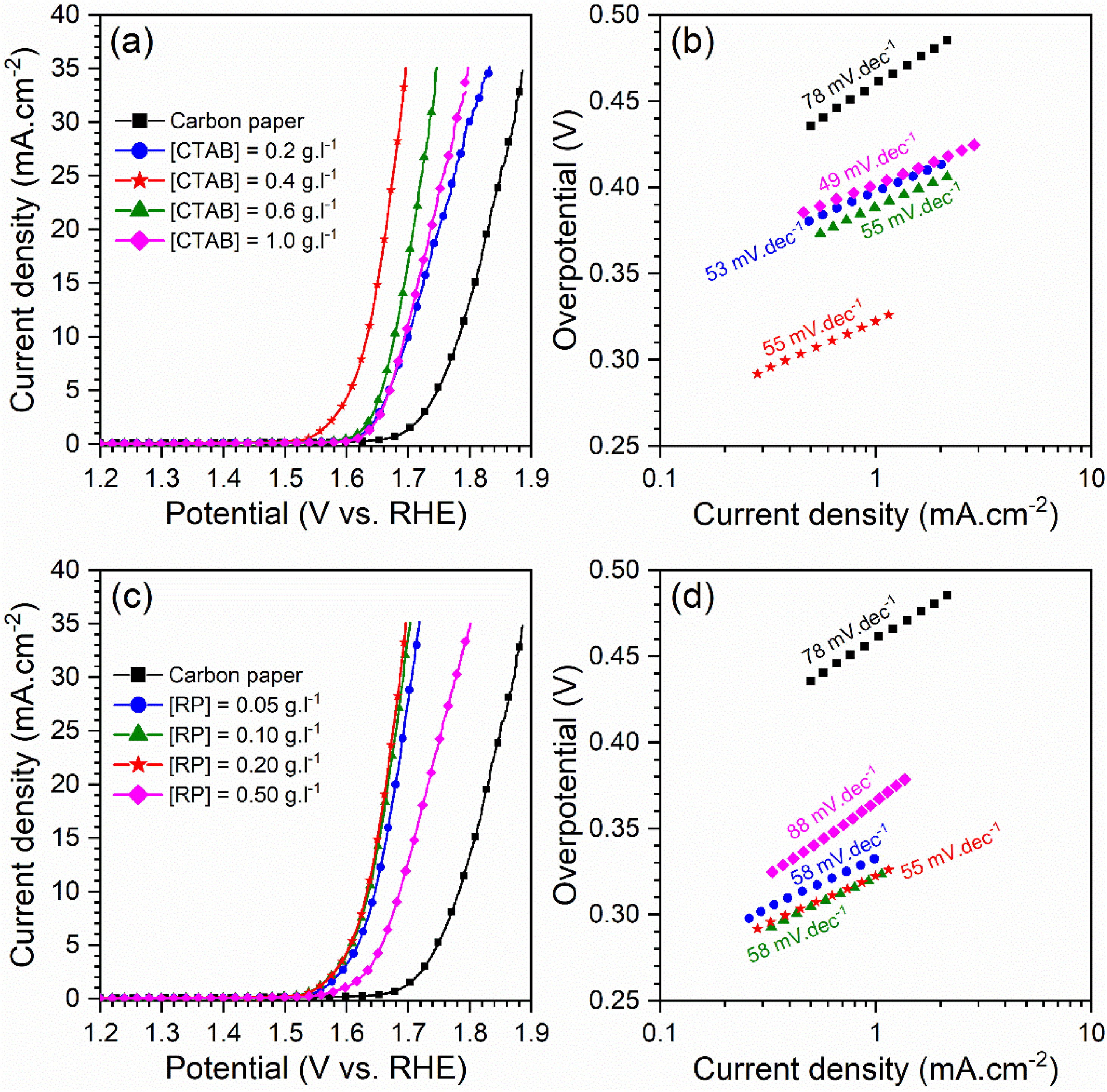
Electrocatalytic behavior of the electrodesFig. 5 displays the LSV curves and corresponding Tafel plots of the bare carbon paper electrode and the electrodes fabricated using different [CTAB] and [RP] in the EPD cell. The OER onset potentials of all electrodes are below 1.6V vs. RHE, which indicates the favorable catalytic activity of electrodes. The electrode with better OER electrocatalytic behavior is located on the left side of the curves. Accordingly, the pristine carbon paper substrate shows the lowest electrocatalytic activity for OER. This result confirms that the presence of the deposited oxide layer improved the catalytic activity of the electrode. On the other hand, the electrocatalytic electrodes deposited with the optimum values of [CTAB] and [RP] showed the highest electrocatalytic activity because of the appropriate homogenous nature of the deposited layer.
 LSV curves at a scan rate of 5mV.s−1 in 1M KOH solution with a pH of 14 and (b and d) corresponding Tafel plots of studied electrodes.")
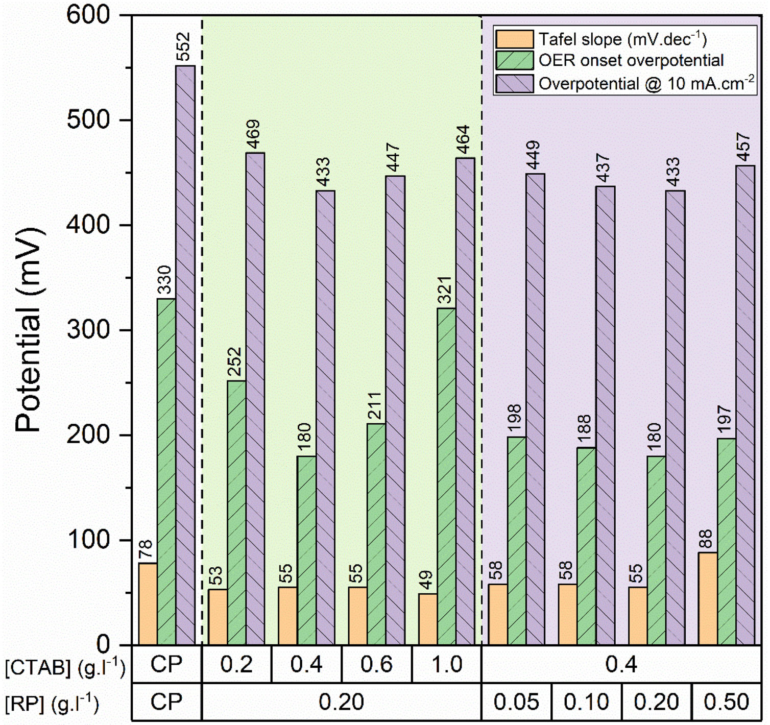
To gain further insight into the electrochemical activity of the electrodes, the main electrochemical parameters of the curves, including Tafel slope, onset overpotential (ηonset), and overpotential at a current density of 10mA.cm−2 (η10), were extracted and plotted in Fig. 6. The variation of ηonset and η10 values revealed that the electrocatalytic performances of electrodes were strongly dependent on the [CTAB] and [RP] in the EPD cell. In this regard, by increasing either [CTAB] or [RP] in the EPD cell, the ηonset and η10 parameters are initially decreased, which indicates the improving catalytic performance of the fabricated electrode. However, for both [CTAB] and [RP] parameters, there is an optimum level of 0.4g.l−1 and of 0.2g.l−1, respectively. Beyond this optimum level, a further increase in either [CTAB] or [RP] led to increasing ηonset and η10, pointing toward a decrease in the catalytic activity of the fabricated electrodes. Accordingly, the ηonset and η10 for the electrode fabricated at the optimum concentrations, i.e. [CTAB] of 0.4g.l−1 and [RP] of 0.2g.l−1, are measured to be 180mV and 433mV, which are ∼ 85% and ∼ 25% lower than of those for bare carbon paper electrode. The highest catalytic activity of the optimum electrode compared to other studied electrodes is attributed to the more homogenous and better distribution of Ruthner powder on the surface, as indicated in Fig. 3. According to the surface morphology micrographs shown in Fig. 3, the participation of a small weight of Ruthner powder on the surface of the electrode deposited at high [CTAB], and the agglomeration of Ruthner powder on the surface of the electrode deposited at high [RP] can be stated as a reason for their lower electrocatalytic performance compared to the optimum electrode.

Fig. 6(b) and (d) show the variation of the Tafel slope for the electrodes fabricated with different [CTAB] and [RP]. Tafel slope is regarded as a measure for electrocatalytic kinetics of an electrode, where an electrode with a higher Tafel slope shows a lower electrocatalytic performance. The bare carbon substrate showed a high Tafel slope of 78mV.dec−1, indicating its low electrocatalytic performance. Apart from the electrode fabricated at [RP] of 0.50g.l−1, the Tafel slope for all the deposited electrodes is almost similar and falls within the range of 49 to 58mV.dec−1 that indicates a similar kinetic mechanism governs in all electrodes due to the presence of Ruthner powder on the surface. The different Tafel slope of the electrode fabricated at [RP] of 0.50g.l−1 can be attributed to the presence of different morphological features on its surface (Fig. 3(h)).
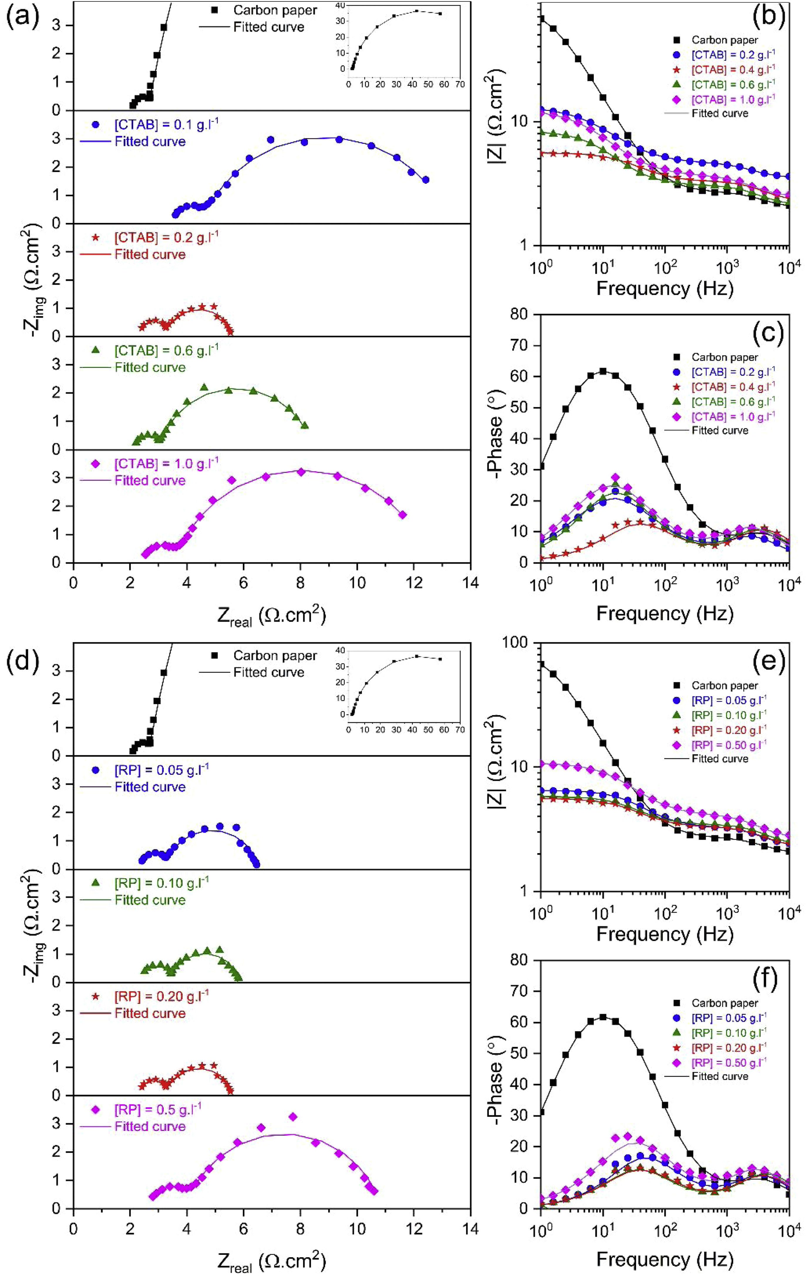
To investigate the electrocatalytic activity of different electrodes fabricated using different [CTAB] and [RP], the EIS response of the electrocatalysts was recorded at a constant applied potential of 0.600V vs. SCE. Based on LSV results, this potential is beyond onset potential for all electrodes, and hence all the studied electrocatalysts show appreciable catalytic activity [43]. Fig. 7 shows the Nyquist and bode plots of different electrodes. Since a full semicircular loop was observed in all Nyquist plots, it can be stated that no mass transport limitation took place during the EIS measurements [44]. Two semicircles were observed in the Nyquist plot of all electrodes, and two corresponding distinct capacitance peaks were observed in the bode phase plot, indicating the dominance of two relaxation processes. The first semicircle observed at the high-frequency region is related to the adsorption/diffusion of reaction intermediates such as MO, MOH, and MOOH, which slowly diffuse through the interface in a porous material [44]. The following second semicircle in the low-frequency region is related to the charge transfer processes, which is regarded as a reference for the redox reaction efficiency [45]. It has been widely accepted that a multiple reaction step determines the rate of the OER process. The OER is a four-electron transfer reaction that in an alkaline solution proceeds in the following steps [46–48]:
![(a) and (d) Nyquist, (b) and (e) bode impedance, (c) and (f) bode phase angle plots of the bare carbon electrode and fabricated electrodes using different [CTAB] and [RP] in the EPD cell.](https://static.elsevier.es/multimedia/03663175/0000006100000004/v1_202207290548/S0366317521000029/v1_202207290548/en/main.assets/gr7.jpeg?xkr=ue/ImdikoIMrsJoerZ+w997EogCnBdOOD93cPFbanNd3TCEZuNxhudow/+3Hrh9WJc+mtnYSSPL9K6mfMWVj1mF0vavFOcplWFUVrNl+WCuP2N/pFLhpdsv8fYsuW88fGJYzti/s8EMN3Mde5LUO1dNCnfQliRY/aNEGPJ2DMKJmeAiraUCs4Kurgz2Xm5GhLtdWZljFFUHpz6/FH2ypZAtjAL230UN1wu8WDH9H8I0gE5C1MVmo/uHiyxrW9elXgD5Fu2Q8dcB1Xs7lbICv54wdCkFAv3oDELEVmBxAm7Ujjyj/E3oQqVI5LoKTKrjG "(a) and (d) Nyquist, (b) and (e) bode impedance, (c) and (f) bode phase angle plots of the bare carbon electrode and fabricated electrodes using different [CTAB] and [RP] in the EPD cell.")
where M stands as the active sites on the surface of metal oxide electrocatalysts.
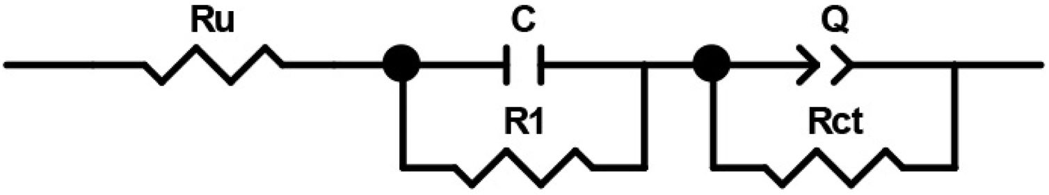
In order to compare the electrocatalytic activity of the studied electrodes, a Ru(R1C1)(RctQ) electrochemical equivalent circuit (EEC) was employed to simulate the electrode/solution interface and to interpret the EIS data (Fig. 8). In this EEC, Ru represents uncompensated electrolyte resistance, (R1C1) is the high-frequency time constant and related to the adsorption of charged surface species on the surface of electrodes, and (RctQ) denotes the charge transfer kinetics of the OER as the low-frequency time constant. The Rct represents the charge transfer resistance and is related to the charge transfer rates of various reaction steps. The element of Q in the EEC is the electrical double layer capacitance. Because of deviation from the ideal capacitive behavior in the studied system, a constant phase element (Q) is used instead of an ideal capacitor to model depressed semicircles arising from heterogeneities and porous surfaces.[49,50] The impedance of Q is expressed as the ZQ=Y0−1(jω)−n, where Yo and n are constants, j=√−1, and ω is the angular frequency [51]. In this equation, n=1 indicates the pure capacitance, n=0.5 implies a Warburg diffusion impedance, n=0 represents the pure resistance, and n=−1 denotes an inductance [52].

The EIS spectra plotted in Fig. 7 were fitted by the Zview/Zplot software using the EEC shown in Fig. 8. The computed values for each element of the EEC are listed in Table 2. The parameter χ2 is the root mean square of the deviations between the data and the fitted curves. The small observed χ2 values for all electrodes indicate that the experimental data could well fit by employed EEC.
Electrochemical characteristics of bare carbon and EPD fabricated electrodes evaluated by EIS.
| [CTAB] (g.l−1) | CP | 0.2 | 0.4 | 0.6 | 1 | 0.4 | 0.4 | 0.4 |
|---|---|---|---|---|---|---|---|---|
| [RP] (g.l−1) | CP | 0.2 | 0.2 | 0.2 | 0.2 | 0.05 | 0.1 | 0.5 |
| Ru (Ω.cm2) | 2 | 3.5 | 2.2 | 2.2 | 2.4 | 2.2 | 2.3 | 2.6 |
| C (μF.cm−2) | 74.7 | 67.4 | 49.2 | 64.1 | 70.3 | 54 | 40.2 | 45.2 |
| R1 (Ω.cm2) | 0.64 | 1.04 | 0.98 | 0.9 | 1.09 | 0.96 | 1.09 | 1.34 |
| Q (mF.sn−1.cm−2) | 1.59 | 5.74 | 4.75 | 5.86 | 5.9 | 2.76 | 4.34 | 2.78 |
| n | 0.9 | 0.77 | 0.86 | 0.85 | 0.8 | 0.88 | 0.88 | 0.83 |
| Rct (Ω.cm2) | 86.1 | 8.7 | 2.3 | 5.4 | 8.9 | 3.2 | 2.4 | 6.8 |
| χ2 (×10−3)* | 0.8 | 0.7 | 1.4 | 0.7 | 0.8 | 1.6 | 1.5 | 2 |
* In all electrodes and for all parameters, the fitting error was less than 10%.
The semicircle in the high-frequency region exhibited relatively small and similar diameter in all electrodes, suggesting fast adsorption and diffusion of reaction intermediates. In contrast, a relatively greater diameter of the second semicircle in the low-frequency region indicates that the charge transfer process is the rate-determined step in fabricated electrodes. In particular, calculation of time constant (τ=R×C) revealed that the time constant at high frequencies is about three orders of magnitudes higher than that at lower frequencies. This result indicates that the Rct controls the kinetic of the OER process in the fabricated electrodes. Obviously, as either [CTAB] or [RP] in the EPD cell increases, the Rct value is initially decreased to a minimum and then increased. Therefore, EIS results, consistent with the LSV findings, demonstrated that the electrode fabricated using [CTAB] of 0.4g.l−1 and [RP] of 0.2g.l−1, showed the lowest Rct values among all studied electrodes and hence possessed the highest catalytic activity.
The electrocatalytic performance of the Ruthner powder electrode was compared with the various iron-based electrodes fabricated by EPD reported in previous literature, and the summary is given in Table 3. Obviously, the Ruthner powder electrode exhibited a competitive performance and can be considered as a promising water oxidation electrocatalyst.
Comparison of electrocatalytic parameters of Ruthner powder and some iron-based electrocatalysts fabricated by EPD.
| Catalysts | Electrolyte | ηonset (mV) | η10 (mV) | Tafel Slope (mV.dec−1) | Reference |
|---|---|---|---|---|---|
| FeOx NPs @ITO | 0.2M PBS* | 580 | – | 110 | [53] |
| FeOx @CFC | 1M KOH | 331 | 441 | 93 | [54] |
| γ-Fe2O3 NW @Fe sheet | 1M NaOH | – | 650 | – | [55] |
| β-FeOOH @FTO | 0.5M PBS | 383 | 590 | 36 | [14] |
| Fe2O3 NPs | 1M KOH | – | 440 | 134 | [19] |
| This work | 1MKOH | 180 | 433 | 55 |
PBS: Phosphate buffer solution; CFC: Carbon fiber cloth; ITO: Indium-doped tin oxide; FTO: Fluorine-doped tin oxide.
In summary, the Ruthner powder –an iron-based waste material is successfully deposited on the carbon paper substrates via EPD to fabricate an efficient electrocatalyst for the OER process. According to our results, [CTAB] and [RP] in the EPD cell significantly affect the morphology and electrocatalytic behavior of the fabricated electrodes. Accordingly, the highest electrocatalytic performance was achieved at [CTAB] of 0.4g.l−1 and [RP] of 0.2g.l−1, where a uniform and homogenous layer of Ruthner powder was deposited on the surface of carbon paper. This electrode exhibited ηonset and η10 as low as 180mV and 433mV, respectively, comparable to the high-efficiency iron-based electrocatalysts. Therefore, the Ruthner powder-based electrodes can be considered as the cost-effective electrocatalyst for water oxidation.
Hakim Sabzevari University is appreciated for providing characterization facilities. Additionally, the support from CEPLANT (Masaryk University, Brno, Czech Republic) is gratefully acknowledged.

