


Highly porous mullite-corundum bodies were prepared by slip casting with the utilization of porogen sources as environmental wastes. The stoichiometric composition of mullite was established by the application of clay and alumina. Pore formers were saw dust or activated charcoal. Bodies were processed, dried and fired between 1180 and 1450°C. Microstructure and the mechanical properties of the product were evaluated. The results showed that, the porosity decreased with raising the firing temperature but the mullite formation increased. The porosity increased with the addition of pore forming agent while modulus of rapture decreasing. The results concluded that the porosity ranged (40–56%) with the addition of pore forming agent (1–10%) with decreasing modulus of rapture (30–8.5MPa) respectively.
Se prepararon piezas de mullita-corindón con elevada porosidad mediante colaje empleando como agentes porógenos residuos ambientales. La composición estequiométrica de la mullita se consigue formulando a partir de arcilla y alúmina. Los formadores de poros empleados han sido serrín o carbón activo. Los materiales fueron procesados, secados y cocidos entre 1.180 y 1.450°C. Se estudiaron la microestructura y las propiedades mecánicas del producto. Los resultados mostraron que la porosidad disminuyó al aumentar la temperatura de cocción, en cambio la formación de mullita aumentó. La porosidad aumentó con la adición del agente formador de poros, mientras que el módulo de ruptura disminuyó. Los resultados han concluido que la porosidad ha aumentado (40-56%) con la adición de agente formador de poros (1-10%) y el módulo de ruptura ha disminuido (30-8,5MPa) respectivamente.
Porous mullite ceramics are characterized, by certain properties, such as; low thermal expansion coefficient, excellent thermal shock, high-temperature creep resistance, good mechanical as well as chemical stability at elevated temperature [1]. The formation of pore structure in ceramics depends on the initial components, the thermal treatment conditions and the burning out of organic additives [2]. Large pores generally originate from the inter-particle spaces between the raw components and are controlled by particle size distribution of the powders, porogen added such as organic additive or graphite [3]. Clay powders or pellets are the most adequate, low cost, ecofriendly raw materials used for their preparation [4–8]. Small pores are formed during phase transformation of de-hydroxylation of kaolin and the main refinement for process of body formation. Porosity of alumina ceramics are affected by; the method of shaping, the organic additive and the ratio of particle size (3.0μm/0.4μm) [9,10]. Attempts were made to utilize admixtures of kaolin and alumina to produce mullite-alumina functionally gradient ceramics [11]. Pores are introduced side-by-side the mullite formation. Usually, the green density, as well as the sintered density increase linearly with the solid content up to an optimum value of 65%. Mullite bodies are produced on firing in air between 1400 and 1600°C. These bodies are characterized by large pores with a pore diameter of ≈100μm. Small cellular pores of 1–10μm are also observed on the internal walls of these pores. Products display a relatively high compressive strength of 1.5MPa and open porosity of 88%. Porous mullite bodies prepared by Rafael Barea et al. [12] showed relatively large spherical-shaped pores distributed within a mullite matrix. The porous bodies were prepared by a direct consolidation method using commercial mullite powder and starch as a pore forming agent. The addition of 45vol % starches gives bodies with 60vol% porosity and average pore size of ∼30μm. Low volume fraction of starch resulted in low porosity %. They together with Ohji [13] fabricated highly porous mullite ceramics by a reaction bonding technique from a powder mixture of Al2O3 and SiC, with graphite particles as the pore-forming agent.
Integration of pyrolyzable pore formers to slip casting slurries [14] is commonly employed methods to fabricate porous ceramics. Meso-porous structure of alumina has a narrow pore size distribution, high specific surface area with good thermal stability compared to conventional alumina. Meso-porous alumina is characterized by surface area 800m2/g and pore size from 2.0 to 10nm [15,16].
The aim of the present work is to produce porous mullite-corundum bodies based on the stoichiometric composition of mullite established by the application of clay and alumina utilizing a porogen source. Microstructure and mechanical properties of the product processed by the slip casting method and fired at 1300 to 1400°C are evaluated.
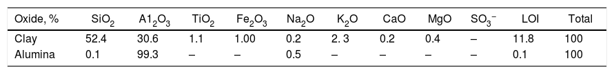
Materials and experimental procedureRaw materialsBall clay (sanbland75) commercial product is from the International Co. WBB (Watts Blake Bearne, Co. PLC). Alumina is from Entrack Co. (Turkish). The chemical composition of raw materials is shown in Table 1. Saw dust with two sizes <63 and <160μm was utilized, as well as activated charcoal powder from El Nasr Pharmaceutical Chemical Co. Egypt (ADWIC), with moisture content 10%.
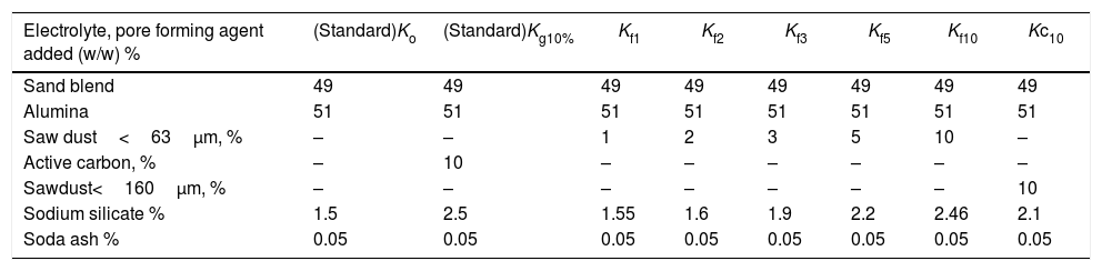
Slip casting technique was used for the preparation of porous mullite. Eight batches based on the stoichiometric composition of mullite were formulated from kaolin (49wt.%) and commercial alumina (51wt.%) with different porogens as saw dust or active carbon as shown in Table 2. Used clay was casted without any addition as reference.
Batch composition of mixes prepared by slip casting process.
| Electrolyte, pore forming agent added (w/w) % | (Standard)Ko | (Standard)Kg10% | Kf1 | Kf2 | Kf3 | Kf5 | Kf10 | Kc10 |
|---|---|---|---|---|---|---|---|---|
| Sand blend | 49 | 49 | 49 | 49 | 49 | 49 | 49 | 49 |
| Alumina | 51 | 51 | 51 | 51 | 51 | 51 | 51 | 51 |
| Saw dust<63μm, % | – | – | 1 | 2 | 3 | 5 | 10 | – |
| Active carbon, % | – | 10 | – | – | – | – | – | – |
| Sawdust<160μm, % | – | – | – | – | – | – | – | 10 |
| Sodium silicate % | 1.5 | 2.5 | 1.55 | 1.6 | 1.9 | 2.2 | 2.46 | 2.1 |
| Soda ash % | 0.05 | 0.05 | 0.05 | 0.05 | 0.05 | 0.05 | 0.05 | 0.05 |
F=Fine saw dust<63μm. C=Coarse dust<160μm.
- a.
The prepared batches were wet ground for 4h in a ball mill with the appropriate percent of defflocculant suitable for each, passed through 63μm sieve, milled to another two hrs; after adding porogen material and adjusting the amount of defflocculant. Milling increase leads to the introduction of a narrow pore size distribution [17].
- b.
Saw dust was added in different proportion namely; 1, 2, 3, 5, 10 (<63μm) as well as 10wt.%. Dust with size of <160μm was added to produce six batches. Besides, the standard mix (Ko) without a porogen and with the addition of 10% graphite (kg).
- c.
The prepared slurries were casted in gypsum molds to produce bar specimens with the following dimensions, 1cm×1cm×10cm. The green specimens were first dried at 110°C for 24h. The change in linear dimensions was recorded for specimens fired in a lab electrical muffle furnace (Carbolite – High Temperature Box Furnace – England) at the following temperatures: 1180, 1250, 1330, 1375, and 1450°C with a soaking period of 1h.
The main rheological properties of the prepared slurries were measured in terms of their viscosity and thixotropic behavior using a Torsion viscometer; type (S.r.l.Sassuolo, Ceramic Instrument Co., Italy). Density of slurries was determined as well. The value of viscosity was followed after the addition of the different proportions of electrolyte to select the proper amount. Green properties in terms of dry linear shrinkage and modulus of rupture (MOR) of the casted bar specimens were determined. While, the physical properties in terms of bulk density, water absorption and the apparent porosity were determined for the bodies fired at different temperatures.
The main crystalline phases developed during firing were identified by XRD using a Philips PW1700 Spectrometer with copper Kα radiation and Ni filter in the range 2θ between 4° and 60°. Specimens fired at the selected temperature were polished, thermally etched at 100°C less than the firing temperature. The surfaces of the specimens were coated with a thin layer of gold 200–300Å by sputtering for 5min. The microstructures of these specimens were examined under SEM equipment (Philips Model X 130).
Results and discussionThe chemical analysis of the clay used in Table 1, shows that the content of silica is relatively high. Moreover, the clay contains a conspicuous amount of fluxing oxides (5%); mainly alkali, alkaline earth and coloring oxides; Fe2O3 and TiO2 (2%). These impurities may affect the high temperature performance of the porous ceramics [18]. Commercial alumina used, is pure with 99% Al2O3. The main constituting minerals of the utilized clay as given by (XRD) are mainly kaolinite beside, quartz.
Ball clay (sanbland 75), main size fraction 64% lies between 0.2 and 20μm and 34% less than 0.2μm; with a surface area as determined by nitrogen absorption equals 24 m2/g [19], while the main size fraction of alumina obtained by sieving shows, that 87% of the material lies between 63 and 180μm, with 13% less than 63μm. These properties have an effective role on the rheological properties of the mixes. Tallon et al. [20] studied that alumina particle size larger than about 300–500nm could lead to low viscosity and high green density. Setz et al. [21] approved that the alumina suspensions have high solid loading due to lamellar morphology of the α-Al2O3 particles and also the particle size (0.7μm).
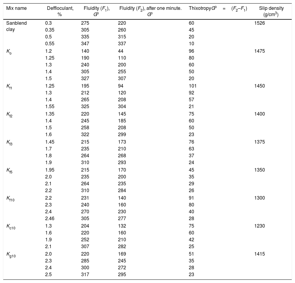
Clay mineralogy and surface properties are the main factors affecting the rheology. The fluidity and thixotropy of the utilized clay is studied (Table 3). The fluidity increased with defluculant addition while thixotropy decreased. Ball clay is plastic in nature and requires deflocculatnts to form stable and non-coagulating slip. So, it consumes high percent of electrolyte 0.55%, slip density 1.5g/cm3 and solid content 30wt.%. The increase of average particle size is the indication of particle flocculation/agglomeration. A well dispersed slurry is obtained when the particles in suspension are kept apart by a complete coverage of charged polymeric layer [22,23] presented by the ultimate concentration of adsorbed polyeletrolyte. The proper amounts of electrolyte to give the required viscosity for each slip batch are given in Table 2 ranged from 1.5 to 2.5wt.%. Soda ash kept constant with changing the sodium silicate. Standard batch needed ≈1.5% sodium silicate, while the other batches consumed more electrolytes ≈2% to adjust viscosity in the direction of increase of the pore forming agent added related with the porogen type.
Rheological properties of used clay and different slip mixes.
| Mix name | Deffloculant, % | Fluidity (F1), Go | Fluidity (F2), after one minute. Go | ThixotropyGo=(F2–F1) | Slip density (g/cm3) |
|---|---|---|---|---|---|
| Sanblend clay | 0.3 | 275 | 220 | 60 | 1526 |
| 0.35 | 305 | 260 | 45 | ||
| 0.5 | 335 | 315 | 20 | ||
| 0.55 | 347 | 337 | 10 | ||
| Ko | 1.2 | 140 | 44 | 96 | 1475 |
| 1.25 | 190 | 110 | 80 | ||
| 1.3 | 240 | 200 | 60 | ||
| 1.4 | 305 | 255 | 50 | ||
| 1.5 | 327 | 307 | 20 | ||
| Kf1 | 1.25 | 195 | 94 | 101 | 1450 |
| 1.3 | 212 | 120 | 92 | ||
| 1.4 | 265 | 208 | 57 | ||
| 1.55 | 325 | 304 | 21 | ||
| Kf2 | 1.35 | 220 | 145 | 75 | 1400 |
| 1.4 | 245 | 185 | 60 | ||
| 1.5 | 258 | 208 | 50 | ||
| 1.6 | 322 | 299 | 23 | ||
| Kf3 | 1.45 | 215 | 173 | 76 | 1375 |
| 1.7 | 235 | 210 | 63 | ||
| 1.8 | 264 | 268 | 37 | ||
| 1.9 | 310 | 293 | 24 | ||
| Kf5 | 1.95 | 215 | 170 | 45 | 1350 |
| 2.0 | 235 | 200 | 35 | ||
| 2.1 | 264 | 235 | 29 | ||
| 2.2 | 310 | 284 | 26 | ||
| Kf10 | 2.2 | 231 | 140 | 91 | 1300 |
| 2.3 | 240 | 160 | 80 | ||
| 2.4 | 270 | 230 | 40 | ||
| 2.46 | 305 | 277 | 28 | ||
| Kc10 | 1.3 | 204 | 132 | 75 | 1230 |
| 1.6 | 220 | 160 | 60 | ||
| 1.9 | 252 | 210 | 42 | ||
| 2.1 | 307 | 282 | 25 | ||
| Kg10 | 2.0 | 220 | 169 | 51 | 1415 |
| 2.3 | 285 | 245 | 35 | ||
| 2.4 | 300 | 272 | 28 | ||
| 2.5 | 317 | 295 | 23 | ||
Rheological properties of different slip mixes are shown in Table 3. The fluidity and density of the slips decreased in the same direction. The density decreased with porogen addition and ranged between 1.5 and 1.2g/cm3. The thixotropy, on the other hand increased. The increase in the volume of the porogen material added resulted in an increase in the viscosity of the slip. Moreover, higher percent of electrolyte was needed to overcome the increase in viscosity. Also, the degree of fineness of the porogen affected the amount of electrolyte. Thus, on comparing mix Kf10 containing fine saw dust needed ≈2.5% electrolyte, while Kc10 containing the same percent but coarse needed ≈2% only. The addition of the same percent, but as fine graphite mix Kg10 consumed 2.5% electrolyte. This result may be attributed to relatively anisometric particles of flake graphite which led to increased particle to particle interactions; their incorporation resulted in a higher viscosity than the relatively isometric particles of spheroidal graphite [24]. Bondioli et al. [25] reported that deflocculants increase the fluidity of aqueous ceramic suspensions. The viscosity will continue to significantly increase depending on the surface charge of the ceramic particles, average particle size and polymeric constituents of porogen used and adsorption of porogen granules onto ceramic surfaces causing tolerable agglomeration [26].
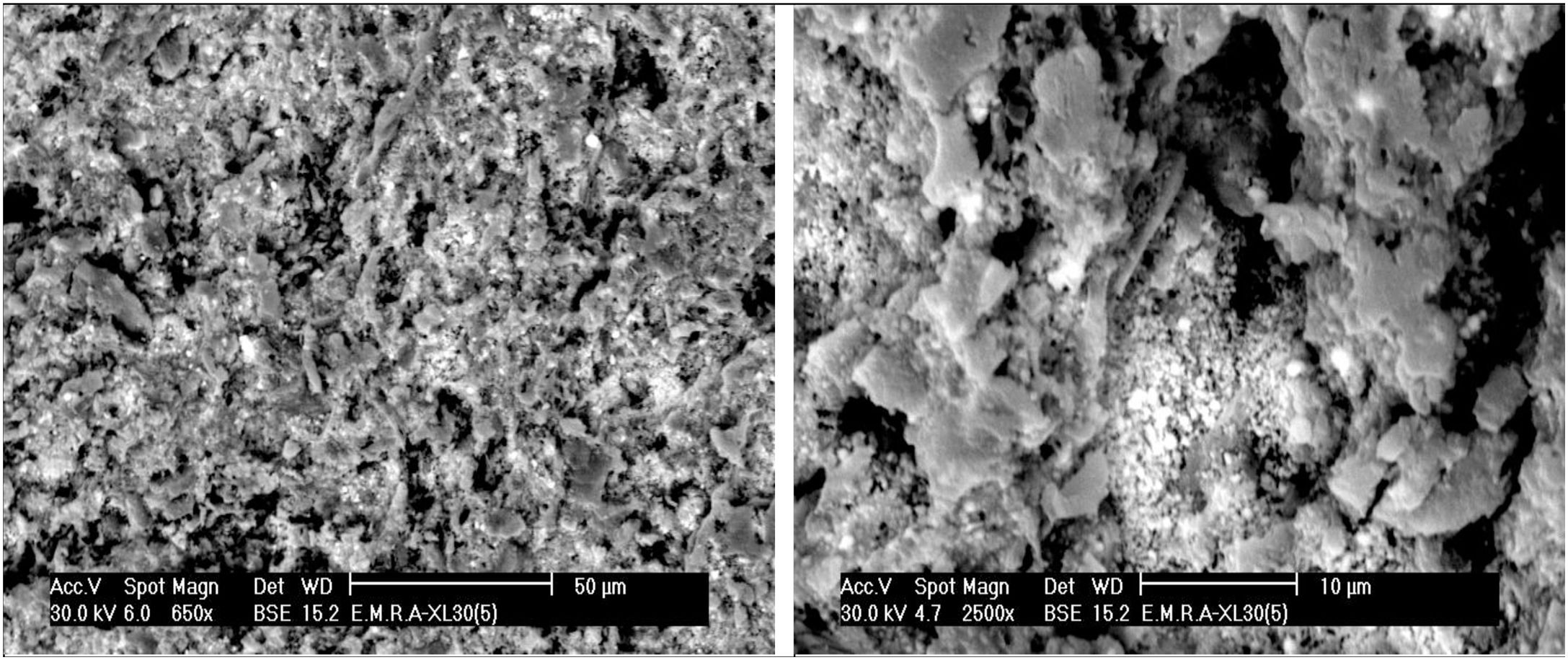
The addition of 10% fine saw dust<63μm showed the same segregation problem as evident from the agglomerates oriented sheets giving mullite agglomerates occurring in bundles of parallel grains. The adjustment of the content of electrolyte to the mix gave a homogeneous matrix. But part of the fine porogen material segregated in small batches leaving pores on firing.
The surface state of the clay particles i.e., the character of adsorbed ions (electro-kinetic-potential) is highly dependent on the type and content of electrolyte dissolved in water, admixtures of other clay minerals, the size distribution, shape of kaolinite crystals as well as aggregates and the stacking degree of kaolin have a substantial influence upon the rheological behavior of clay. The coarse vermicular crystals of clay i.e. those partially delaminated cause a substantial increase of viscosity of suspensions. Therefore, the complete delamination of the clay component is necessary. Moreover, the flow properties of the casting slips are closely related to the degree of internal lubrication, which is mainly influenced by the amount and fineness of the colloidal particles (0.5–0.001μm) and optimum particle dispersion.
Phelps et al. [27] showed the favorable effect of small amounts of fine particles in much larger volume of relatively coarse particles and grains in non-clay slips on the flow of concentrated suspensions, previously discovered by Clarke [28]. According to Reiner [29] the smaller particles fill the interstitial spaces of the coarse grains, forcing previously immobilized liquid out to increase fluidity, a distribution obeying the criteria for minimum voids described by Fuller and Thopson; Furnas [30,31] However, since all particles tend to absorb layers of liquid the progressively increasing colloidal fractions may reduce the free liquid by adsorption, met with in case of admixtures of montmorillonite and illite. High solid content of casted slip is required. It is therefore necessary to induce the highest possible mutually repulsive force between charged particles of like sign [32].
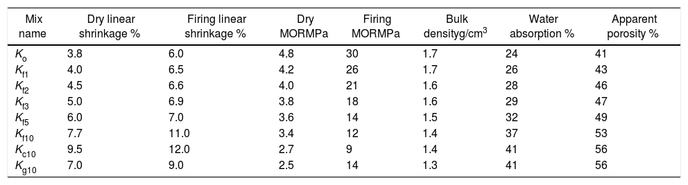
The physical properties of the dried and fired bodies are shown in Table 4. The dry linear shrinkage of the green bodies increased with the percent of saw dust added, while the dry strength decreased. This may be attributed to the network structure of green bodies due to polymeric action of lignocellulosic materials produced from saw dust grinding at low temperature and dissociated while drying [33]. The values of dry strength are related to inter-locking of the particles when the water was removed. So the addition of saw dust gradually decreased the dry strength and the percent of the dry linear shrinkage, as demonstrated by the results of mixes.
Physical properties of specimens of porous ceramic bodies, green and fired at 1330°C.
| Mix name | Dry linear shrinkage % | Firing linear shrinkage % | Dry MORMPa | Firing MORMPa | Bulk densityg/cm3 | Water absorption % | Apparent porosity % |
|---|---|---|---|---|---|---|---|
| Ko | 3.8 | 6.0 | 4.8 | 30 | 1.7 | 24 | 41 |
| Kf1 | 4.0 | 6.5 | 4.2 | 26 | 1.7 | 26 | 43 |
| Kf2 | 4.5 | 6.6 | 4.0 | 21 | 1.6 | 28 | 46 |
| Kf3 | 5.0 | 6.9 | 3.8 | 18 | 1.6 | 29 | 47 |
| Kf5 | 6.0 | 7.0 | 3.6 | 14 | 1.5 | 32 | 49 |
| Kf10 | 7.7 | 11.0 | 3.4 | 12 | 1.4 | 37 | 53 |
| Kc10 | 9.5 | 12.0 | 2.7 | 9 | 1.4 | 41 | 56 |
| Kg10 | 7.0 | 9.0 | 2.5 | 14 | 1.3 | 41 | 56 |
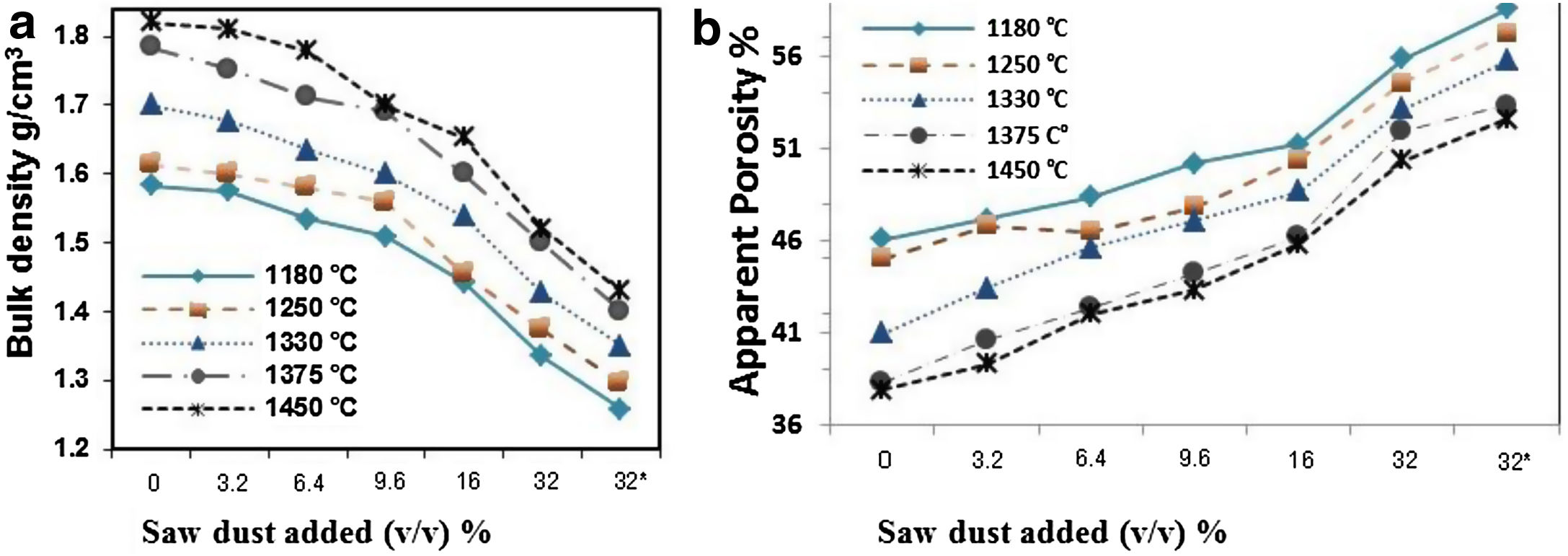
Densification of fired porous bodies was monitored by measuring linear firing shrinkage, bulk density, water absorption as well as apparent porosity. From the results obtained, there was a general trend displayed by all mixes; water absorption and apparent porosity decreased with rise in firing temperature. The bulk density on the other hand, increased. Porosity values were proportional to the amount of saw dust added following a linear relation. But, they negatively affected the strength of the bodies produced. These results are in good agreement with the previous works [34,35].
The physical properties of the fired bodies change with pore former added. Results show that the firing shrinkage was affected by the temperature of firing and the content of porogen material added. Higher proportion of porogen caused higher shrinkage values accompanied by low density and MOR, Table 4. Apparent porosity on the other hand, increased. But, raising the firing temperature reduced the porosity, as shown in Fig. 1.

Two different porogen materials were used in formulating some of the mixes. Thus, the same proportion from both porogen materials, fine graphite and saw dust with two grain size coarse<163μm as well as fine<63μm were utilized. The type of porogen material was greatly affected the bulk density and apparent porosity. The standard mix Ko showed a bulk density of 1.7g/cm3 and strength of 30MPa and an apparent porosity of 40%; This is attributed due to the absence of pore forming agent and the existence of rod-shaped mullite crystals embedded in the glassy matrix, improving thereby the mechanical performance. The density was reduced to 1.34g/cm3 and the apparent porosity reached 56%, in Kg10.
Graphite is a competitive pore forming agent as evident when compared with other pore former particles at the same volumetric loading. The coarse dust showed higher porosity than the fine dust due to relatively isometric of fine particles [24]. The MOR of specimens fired at 1330°C was greatly affected by the content of porogen material added. The lowest value 8.5MPa was obtained by the mix containing coarse dust compared with 13.7MPa for fine graphite and 11.9MPa for the fine dust. The irregular, connected and larger pores are formed in the porous ceramics due to the agglomeration and non-uniformity of pore-forming agents [36,37], leading to the lower strength [38].
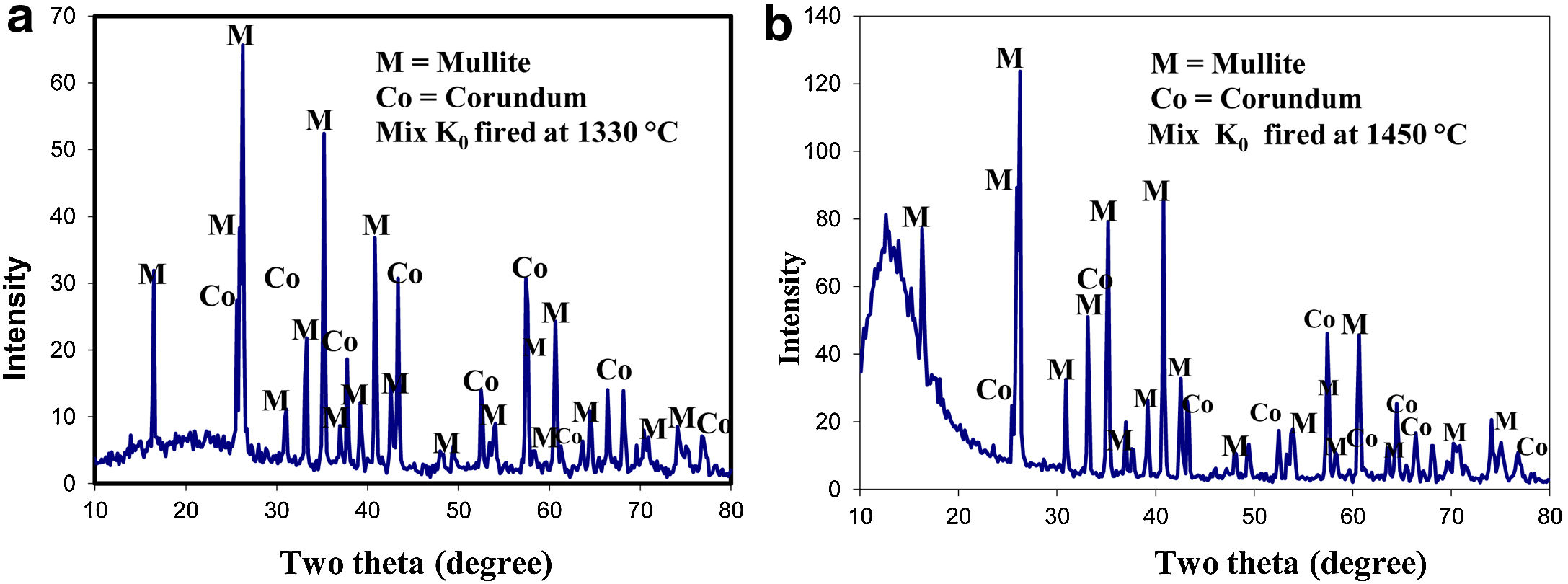
Results of XRD of the selected mixes at the maturing temperature for each are demonstrated in Fig. 2. All mixes showed the formation of the mullite phase as a result of the reaction of alumina and silica of the different raw materials but in various proportions. Residual alumina was left un-reacted giving corundum (α-alumina phase). No trace of silica was detected in specimens fired at 1330°C.
 1330°C, (b) 1450°C. Identification card numbers to phases: Mix Ko fired at 1330°C. Mullite: 06-0259 and Corundum: 81-2267 & mix Ko fired at 1450°C. mullite: 83-1881, corundum: 74-1081.")
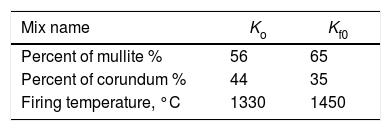
The effect of the different precursors on mullite formation in the present study was followed in bodies fired at 1330°C, the selected temperature. The number of XRD counts obtained for the selected d spacing 2.20, 1.741 Angstrom, at 2θ=40.84, 52.516 degree for mullite and corundum, respectively.
XRD of standard mix Ko was fired at two different temperatures: 1330 as well as 1450°C, is shown in (Fig. 2). Mullite is the main crystalline phase developed. The number of counts gave an idea about the degree of crystallinity of the mullite formed and its content. The specimens fired at 1450°C gave higher percent of better crystalline phase compared with that fired at 1330°C. Meanwhile, the peaks of the relic corundum phase, was greatly reduced. No signs for quartz or any other silica phase was detected.
The number of XRD counts denotes the extent of mullite formed in a particular mix. It is affected by batch composition, grain size of alumina added, percent and grain size of the porogen utilized. In these mixes; the mullite formed based primarily on kaolinite content. Firing at 1450°C caused the amount of mullite formed to be doubled, but still rest of corundum was left unreacted as shown in Table 5. This indicates the need of a higher temperature for the completion of the reaction.
Maximum counts for mullite [Mullite phase at 2θ:40.84 – d: 2.20] was detected in matured ceramic mixes containing clay and fine alumina, compared with mixes from kaolinitic clay only. Corundum [Corundum phase at 2θ: 52.516 – d: 1.741] was also detected in most mixes but no quartz was found. The amount of mullite formed is double that of Ko fired at the different temperatures.
The existence of glassy silica phase creates small pore sizes accompanying the sintering shrinkage process that reduces the open porosity. The addition of Al2O3 wt.% to clays or active silica provides more alumina to react with the glassy silica and thus inhibits sintering shrinkage as the Al2O3 particles act as a skeleton creating a high porosity as long as the sintering process occurs at 1400°C or below [39–41]. The reaction of kaolinite with alumina is of interest in the production of mullite. The study carried out by Liu et al. [40] showed that cristobalite formation in kaolinite is retarded by the presence of alumina between 1250 and 1350°C and was totally prohibited above 1380°C due to the formation of secondary mullite by the reaction of alumina with this silica. This reaction is initiated at 1250°C and becomes more pronounced above 1380°C and extremely fast at 1600°C.
An orientation of the formed mullite takes place during crystallization on the edge-on platelets, owing to the previous alignment of the plate like shape kaolinite particles. This view was also demonstrated by Chen et al. [42]. They stated that mullite grains have originated from the edge of kaolinite flakes then tend to grow along the flat surface of the flakes and therefore showed preferred orientation. The kaolinite crystal is composed of (Si2O5)2− layer and [Al2(OH)4]2+ layer. The Si as well as Al ions are stacked sequentially in the direction of the c-axis paving for the crystallization of mullite at low temperatures. But the mullite needles crystallize from a liquid melt which encourages the exposure of low energy crystallographic faces.
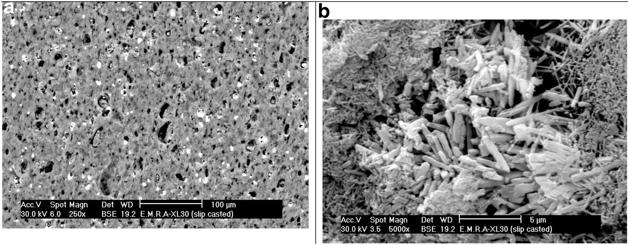
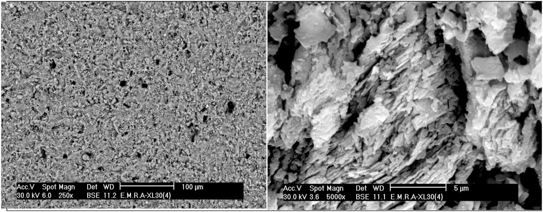
SEM of the raw clay sample delivered in the form of noodles by the producer and as processed bars by slip casting after being fired at 1330°C was examined under SEM. The fired noodles showed a kind of orientation of the raw clay mineral sheets as evident from the SEM showing agglomerates where the mullite prisms were gathered. Fired slip cast processed bar specimens showed two types of the mullite phase, a homogeneous distribution of primary mullite as minute grains in agglomerates originating from the clay matrix, as well as mullite prisms was crystallizing out from the liquid phase occurring in agglomerates too, as evident from the SEM displayed in Fig. 3.
 No orientation of clay sheets. (b) Both types of mullite phase are present as fine needles and large prismatic grains.")
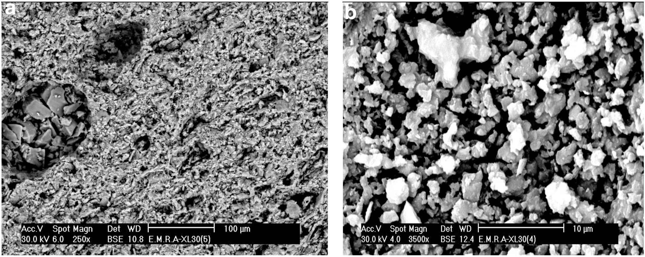
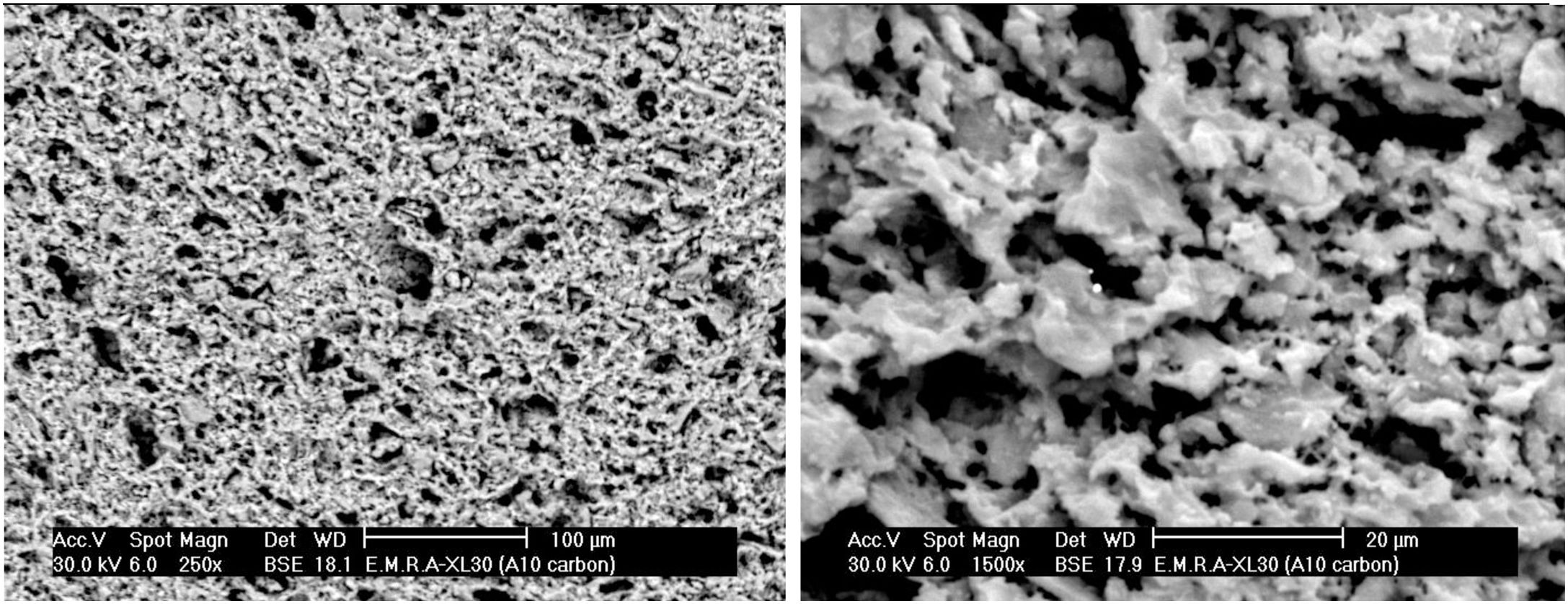
The microstructure of standard mix Ko with or without the addition of porogen material processed by slip casting, showed a kind of segregation of the different components. The percent of electrolyte of mix Ko was adjusted and as a result the different components were well mixed and homogeneously distributed as shown in the SEM, displayed in Fig. 4. The addition of 10% fine saw dust<63μm showed the same segregation problem as evident from the agglomerates of oriented sheets giving mullite agglomerates occurring in bundles of parallel grains. The adjustment of the content of electrolyte to the mix gave a homogeneous matrix. But part of the fine porogen material segregated in small batches leaving pores on firing as displayed in Fig. 5. The content and type of porogen material added affected the microstructure developed of the different mixes. Fig. 6 shows the effect of the addition of graphite as porogen material. The graphite was homogeneously distributed in the matrix leaving fine pores on burning out compared with the saw dust. Moreover, the particle size of the porogen material added influenced the size and content of pores present. The segregation problem was more obvious when coarse saw dust<160μm was added (Fig. 7).


Herein, porous mullite ceramics were ecofriendly prepared from raw materials; clay and commercial alumina, with environmental wastes (saw dust and graphite) as pore forming agent. Slip casting as low cost and efficient technique was used. The effect of pore former additions and deffloculants on the rheological properties of mixes, were followed. Whereas, the influence of firing temperature, pore former on the mechanical performance and the porosity of porous mullite ceramics were investigated. The porosity decreased with raising the firing temperature, while the mullite formation increased. Activated charcoal powder as pore forming agent was replaced by 10% saw dust, as a result, organized pores with highest apparent porosity 56% sintered at 1330°C, were achieved. Finally, the results concluded that the porosity ranged (40–56%) with the addition of pore forming agent (1–10%) with a decrease in modulus of rapture from 30 to 8.5MPa.

