


Metakaolinite was obtained by thermal treatment of natural kaolinite. Both of them, kaolinite with structurally bonded water and metakaolinite without it, were, after sieving to acceptable size fraction, plasma sprayed. The coatings were rather lightweight and composed predominantly of amorphous material. Stainless steel was used for producing self standing deposits, whereas other materials like carbon steel or ceramic tiles formed a permanent substrate-coating system. Metakaolinite coating was less porous, harder and its thermal behavior was simpler compared to kaolinite. Crystallization and formation of secondary phases was monitored after annealing with and without dust particles known in the barrier coatings field as CMAS.
La metacaolinita se obtuvo por tratamiento térmico de caolinita natural. Ambos, caolinita con agua ligada estructuralmente y metacaolinita sin ella, después de tamizar a una fracción de tamaño aceptable, se proyectó mediante un plasma. Los revestimientos eran bastante porosos y estaban compuestos predominantemente de material amorfo. El acero inoxidable se usó para realizar depósitos independientes, mientras que otros materiales como el acero al carbono o las baldosas cerámicas formaron un sistema permanente de revestimiento de sustrato. El recubrimiento de metacaolinita fue menos poroso, más duro y su comportamiento térmico fue más simple en comparación con la caolinita. La cristalización y la formación de fases secundarias se controlaron después del recocido con y sin partículas de polvo conocidas en el campo de las barreras térmicas como CMAS.
Kaolinite is a widespread mineral and constituent of many porcelain and ceramic products, especially in the branch of utility ceramics. Kaolin, relatively pure clay, has been widely used in ceramic industries for centuries [1]. Kaolin is a white sedimentary rock originating from chemical weathering (kaolinization) or by hydrothermal alteration of rocks rich in feldspar – mainly granites, pegmatites, and arkoses. Kaolin is constituted by the mineral kaolinite from more than 80%, accompanied with silica and a variety of clay minerals, micas, feldspar and others according to the nature of the mother rock.
Before using kaolinite in some applications, heating is desirable. This treatment is called dehydroxylation or calcination. It runs initially between 550 and 750°C, where dehydroxylation takes place, i.e. bonded water is released [2]. At the same time, Al-octahedrons of the clay mineral are reformed to Al-tetrahedrons. Stable finely crystalline kaolinite transforms to metastable and non-crystalline metakaolinite this way [3–5].
If the temperature of treatment rises over 900°C, crystalline mullite (Al6Si2O13), spinel (MgAl2O4) or γ-Al2O3 with amorphous silica (SiO2) are formed. This process depends on the content of alumina and silica.
The principle behind thermal spray is following: (i) to melt the feedstock powder, (ii) to accelerate the melt and (iii) to impact on a substrate where rapid solidification and deposit build-up occur. High melting temperature is achieved electrically (in an electric arc), which ionizes gas or water representing the plasma forming medium (in case of a WSP-H system used here, water is the medium) to form a plasma jet accelerating the molten particles to the target substrate, where the material solidifies forming a deposit. The deposit is built-up by successive impingement of these individual flattened particles called “splats” [8]. Successive passes of the plasma jet over the substrate (spray trajectory) is carried out by a robotic arm or another programmable manipulator.
Plasma spray process is used to fabricate deposits more than 50°C thick from a wide range of industrial materials including ceramics. Minerals of natural purity have been applied as well [9–12]. However, plasma spraying of such material as kaolinite, exhibiting both following obstacles: structurally bonded water and a narrow melting interval/incongruent melting, is considered extremely difficult. That is the main challenge of the actual experiments. Kaolinite could serve as a low-cost environmental barrier coating and once thermally transformed, also as a low-cost thermal barrier coating for not extremely high temperatures and medium harsh environments [13].
Besides pioneer plasma spraying of kaolinite, we also studied chemical reactions of our coatings with a silicate based dust. After the main oxides forming such dust, i.e. CaO, MgO, Al2O3 and SiO2, the label CMAS is usually applied for it [14]. Examination of chemical reactions of thermal barrier coatings with powders like CMAS is essential for application where aircraft parts covered by protective coatings are open toward the environment and dangerous dust during service. At a high temperature, CMAS melts and infiltrates into the coating along the pores and microcracks rapidly. Upon cooling, CMAS penetrated into the coating solidifies, and blocked pores develop a high stress level. Also for other barrier coating applications like in land-based turbines, the interaction with CMAS is important to be studied.
ExperimentalPowders and sprayingKaolin for this study comes from the Kaznějov deposit in western Bohemia, Czech Republic. The parent rocks are Upper Carboniferous arkose and arkose sandstone. The main components are quartz (50–70%) and kaolinite (20–30%) with accompanying micas and feldspar in various intensity of disintegration. Accessories are mostly represented by Ti-ilmenite, rutile, leucoxene, anatase, tourmaline, garnet and Fe-oxides and hydroxides. The main product of the quarry is floated kaolin which was used in our experiments.
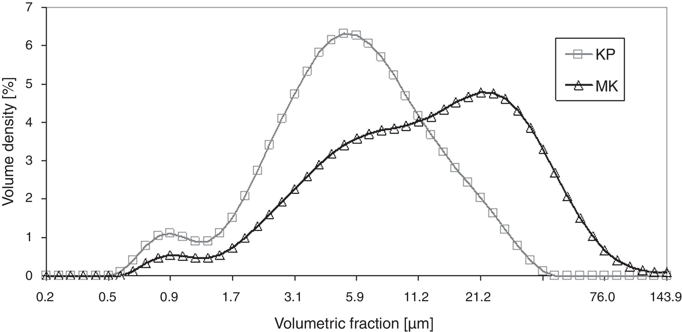
The X-ray diffraction data (XRD) of starting kaolin powder (labeled KP) showed fully crystalline material composed of kaolinite 75%, muscovite 19%, and silica 6%. The material was sieved to powder fraction displayed in Fig. 1.
 and metakaolinite (MK) powders.")
Powder size distribution curves, Fig. 1, show a certain degree of sintering of metakaolinite (labeled MK; see below for details of its preparation), which was reflected in a higher average size of powder particles – i.e. peak centered at 20μm instead of 4μm. Volume density of the smallest particles (the “tail” at about 1μm) decreased in terms of Volume density for metakaolinite.
Enthalpy of kaolinite tends to increase with temperature [15]. Removal of the bonded water consumes lot of plasma energy, proper melting is rather complicated, and therefore searching for the parameters for optimal spraying was relatively difficult. Incongruent melting was reported at presence of free SiO2 in kaolinite [16]. DTA showed broad endotherms at the dehydroxylation temperature of 526.2°C and 521.3°C [17]. Dehydroxylation of our feedstock material KP was finished at about 650°C. More details are described below.
Thermal treatment of the powder to reform kaolinite powder (KP) into metakaolinite (MK), and to remove bonded water, was done in a laboratory furnace, in air atmosphere at 700°C, with the dwell time 30min and ramp up and down 7°C/min.
A loss of 10.3% of the original mass was detected after the treatment, which is caused by dehydration and dehydroxylation. Phase analysis done by XRD showed 97% of amorphous material (i.e. metakaolinite). The relative content of phases was 38% silica and 62% muscovite, whereas the quantity of the components is counted from the 3% of crystalline material. Metakaolinite originated partly from the transformed kaolinite and partly from silica and muscovite. The mass loss of metakaolinite compared to kaolinite was estimated in the literature [18] to be 9% (surface adsorbed water plus hydroxyl groups).
Plasma spraying was done by a hybrid water-stabilized plasma torch (WSP-H). Plasma spray setup was optimized by studying single splats and free flight particles (i.e. particles collected before reaching the substrate). Shorter feeding distance (axial distance between the plasma nozzle and the injector, FD) led to evaporation of the sprayed material resulting in nearly zero spray efficiency monitored by the thickness growth speed. Longer FD caused extremely porous coating with poor cohesion due to insufficient powder melting.
Shorter spray distance (axial distance between the plasma nozzle and the substrate, SD) induced delamination of the coating (delamination within the coating, not a release from the substrate). Longer SD led to too cold impact and very low thickness growth speed (i.e. poor spraying effectiveness).
Preheating of the substrate for spraying was carried out by the torch, always to 120°C, and between passes over the substrate the temperature was monitored and maintained at 125°C. Torch current 500 A was applied and powder feeding ensured by air.
Spraying of the final coating based on the original kaolinite powder was performed at the feeding distance (FD) 55mm, spray distance (SD) 270mm, onto a stainless steel substrate, using 16 passes over the substrate with the final thickness about 0.85mm (i.e. thickness per pass 53μm).
Spraying of the coating based on the treated powder (MK) was performed by WSP-H using feeding distance 50mm, spray distance 250mm and 26 passes over the substrate to gain thickness about 1.50mm (i.e. thickness per pass 60μm).
Depending on the substrate material, the coatings of KP and MK adhered on the substrate or were released during cooling to form self-standing plates. Stainless steel was used for this, whereas other materials like carbon steel or ceramic tiles formed permanent substrate-coating systems.
Characterization techniquesPhase compositionThe types of crystalline phases, their amount and degree of crystallinity of sprayed coatings and feedstock powder samples were analyzed by X-ray diffraction. All samples were measured in the same manner on Bruker D8 Advance diffractometer in Bragg-Brentano geometry with Cu-Kα radiation and 1D LynxEye detector. Precise alignment of the sample surfaces was done by laser. Topas software version 4.2 was used for quantitative Rietveld analysis. The amorphous material was assumed to be of the same chemical composition, so crystallinity was computed from integral intensities of crystalline phases and amorphous haloes only.
X-ray fluorescence was performed using spectrometer Axios (Panalytical, NL) equipped with Rh tube, 4kW generator, 3 collimators, 8 crystals, and data processed with the software Omnian for a standard-less analysis.
Thermal analysesDifferential thermal analysis (DTA) curves were obtained by simultaneous thermal analyzer (TG-DTA, Bähr, Germany) using a B-type thermocouple. A heating rate of 10°C/min was applied up to 1600°C in a dynamic oxidative atmosphere (synthetic air flow rate 5l/h). Thermal treatment of the powders and crushed coatings took place in alumina crucibles. The results were corrected by blank subtraction and the data are presented as being recalculated per gram of the sample.
Thermal expansion of the as-sprayed coatings (i.e. after spraying without any thermal post-treatment) was studied by a vertical push rod dilatometer TMA Setsys 16/18 (Setaram, France). Measurement was done on a free-standing (removed from the substrate) samples 8mm (KP) and 10mm (MK) long in a controlled air flow. Heating rate of 10°C/min was used in the temperature range 30–1550°C. A load of 5g was applied. The obtained data were corrected by blank subtraction.
Thermal diffusivity of the free-standing coatings was measured by a laser flash apparatus LFA 1000 (Linseis, Germany). The measuring was held in vacuum at a room temperature and at temperatures from 100°C to 1300°C with a step of 200°C. Sample thickness was 0.8mm (KP) and 1.3mm (MK). The coatings were slightly ground to obtain smooth surface on which a thin layer of gold was applied before covering with colloidal graphite. The resulting values of thermal diffusivity were calculated as an average from five measurements at each temperature.
MicrostructureThe samples were sectioned using a diamond cutting blade and cross sections were mounted in a low viscosity resin. Metallographically polished cross-sections were prepared from as-deposited coatings. Grinding and polishing of the samples were carried out using an automatic polishing system Tegramin-25 (Struers, Denmark). Cross-sections of the samples were observed in a light microscope Neophot 32 (Carl Zeiss SMT, Germany) and in a scanning electron microscope (SEM) Mira II LMU (Tescan, Brno, CZ) equipped with an energy dispersive X-ray detector (EDX). Prior to observation, the specimens were coated by a thin layer of gold (powders and coatings surfaces) or carbon (polished cross sections) in a sputter coater to ensure signal stability and specimen discharging. The microstructure was investigated with a back scattered electron (BSE) detector, since BSE provide better stability of signal necessary for powder investigation. The accelerated voltage was set on the 15kV and the working distance was changed during scanning from approximately 13 to 22mm.
Porosity, microhardness and roughnessPorosity was studied by optical microscopy on polished cross-sections. Micrographs were taken with a CCD camera and processed using image analysis (IA) software Lucia G (Laboratory Imaging, Czech Rep.). Porosity levels were determined by image analysis (IA) based on differentiating between porosity and bulk coating by the grey levels. Reported values are averages from 10 frames collected at 250× magnification. In addition to a simple quantification of porosity, other pore features were also examined. Circularity of pores (planar 2D projections) is equal to zero for a line and 1 for a circle. A plasma sprayed coating contains typically pores flattened parallel to the surface as a result of the lamellae (so called splat) formation. Size of the pores was represented by Equivalent Diameter (ED). Density was determined by Archimedes principle (i.e. water immersion). Specific weight was examined by helium pycnometry (Accu-Pyc 1330 V3.03; Micromeritics, USA).
Vickers microhardness of the coatings was measured on polished cross-sections by an optical microscope equipped with a Hanemann head and a Vickers indenter using a 0.5N load applied over 15s. The mean value of microhardness was calculated as an average from 20 indentations. Surface roughness was determined by a contact method using the Surtronic 3P (Taylor-Hobson, UK) apparatus on a path length of 13mm repeated 5 times on various parallel tracks.
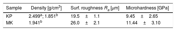
Results and discussionCoating microstructureSpecific weight of the deposited KP coating was low (2.499±0.017g/cm3 by pycnometry), and from this standpoint, kaolinite belongs to the most lightweight materials ever plasma sprayed, like spodumene (1.64–1.88g/cm3, porosity 18.5%) or tourmaline (1.67g/cm3, porosity 30.8%) [10]. Open porosity of the KP coating, examined by the Archimedean technique, was 24.12% while open porosity of MK coating was only 8.70%. Most typical ceramic coatings have much higher specific weight, between 4 and 6g/cm3.
Fig. 1 displays the size distribution curves of KP and MK powders. Because of structural aspects mentioned below, the curves are rather different.
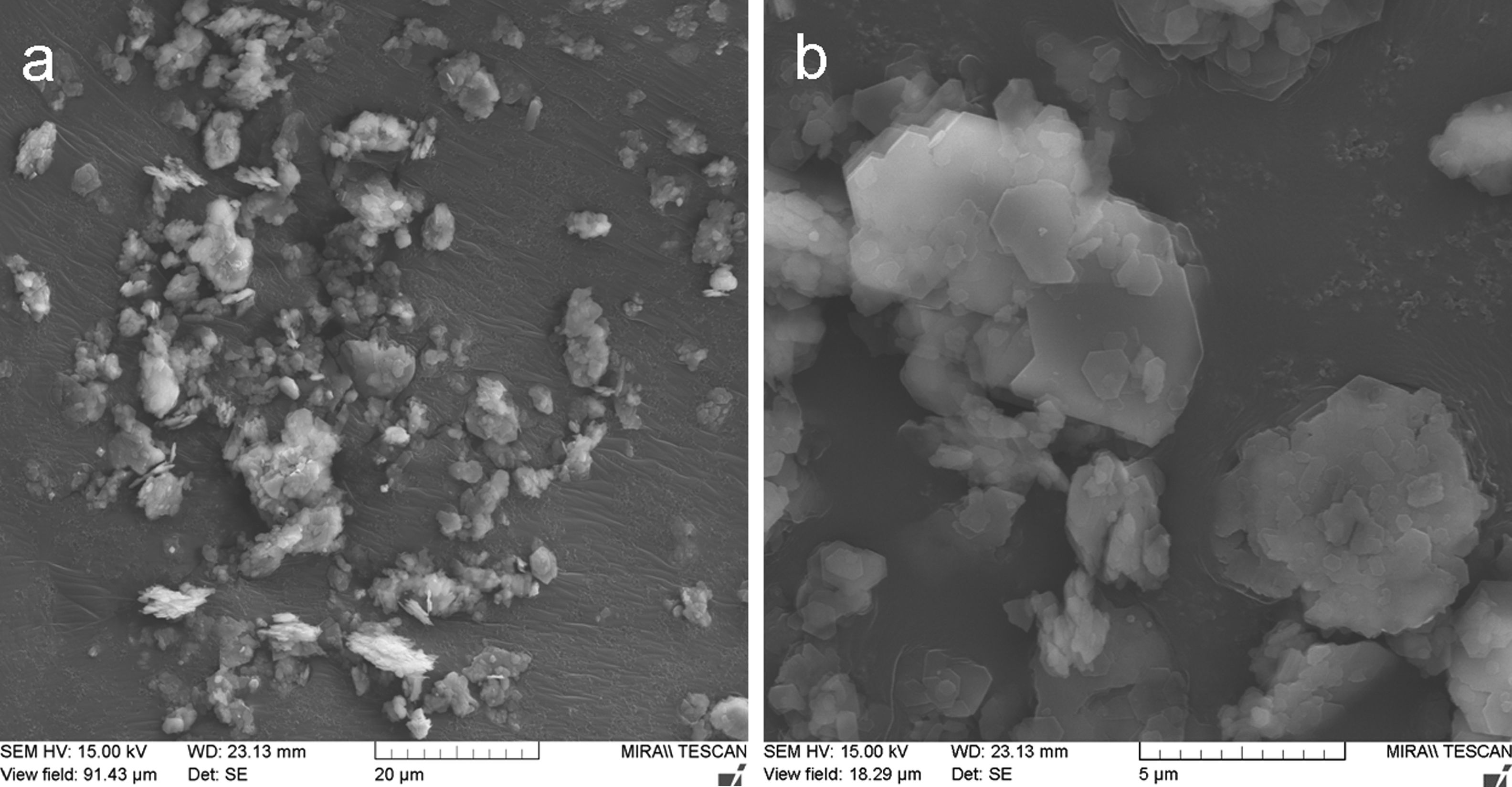
Fig. 2 shows the original powder morphology. Especially the KP feedstock contained micro-flakes that formed larger agglomerated particles, but during handling the powder, the micro-flakes were partly separated from each other, which is an unwanted phenomenon and makes the powder too fragile and transport-sensitive (with a difficulty to establish a reliable size fraction).
 Micrograph of the kaolinite spray powder. (b) Micrograph of the kaolinite spray powder – detail.")
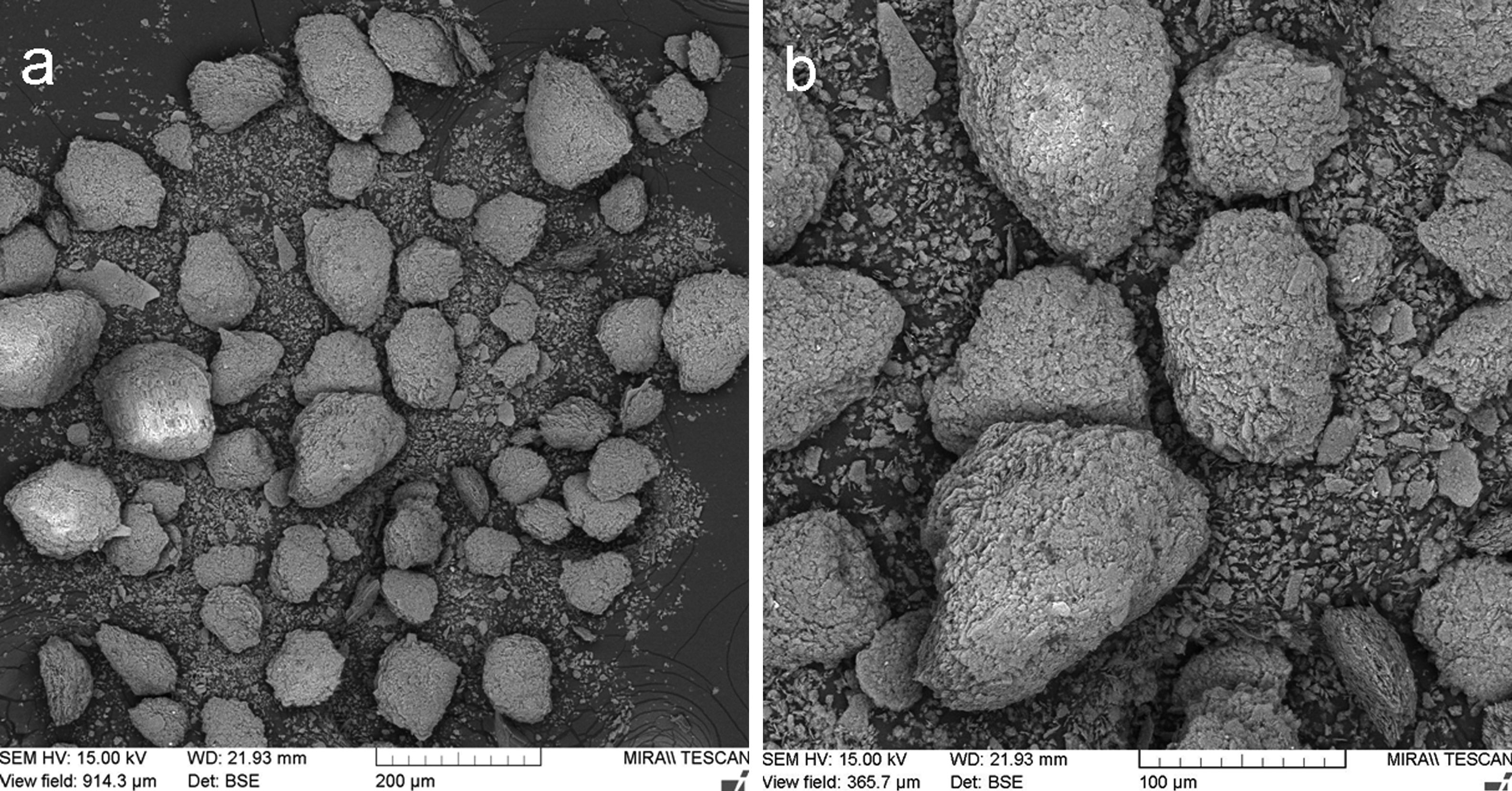
Metakaolinite powder, Fig. 3a and b, exhibited improved cohesion due to thermal treatment applied – the micro-flakes were partly fused together and formed granulated feedstock powder suitable for plasma spraying (Table 1).
 Micrograph of the metakaolinite spray powder. (b) Micrograph of the metakaolinite spray powder – detail.")
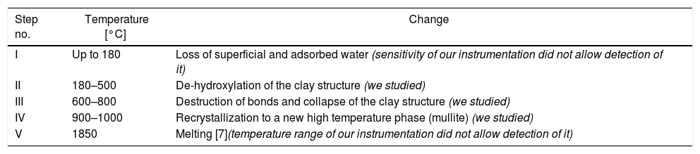
Transformations in kaolin structure during firing – based on literature.[6].
| Step no. | Temperature [°C] | Change |
|---|---|---|
| I | Up to 180 | Loss of superficial and adsorbed water (sensitivity of our instrumentation did not allow detection of it) |
| II | 180–500 | De-hydroxylation of the clay structure (we studied) |
| III | 600–800 | Destruction of bonds and collapse of the clay structure (we studied) |
| IV | 900–1000 | Recrystallization to a new high temperature phase (mullite) (we studied) |
| V | 1850 | Melting [7](temperature range of our instrumentation did not allow detection of it) |
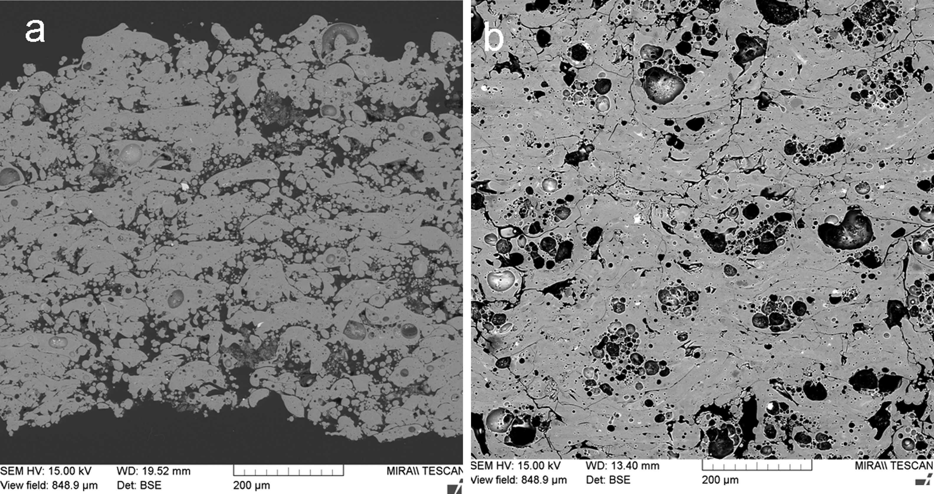
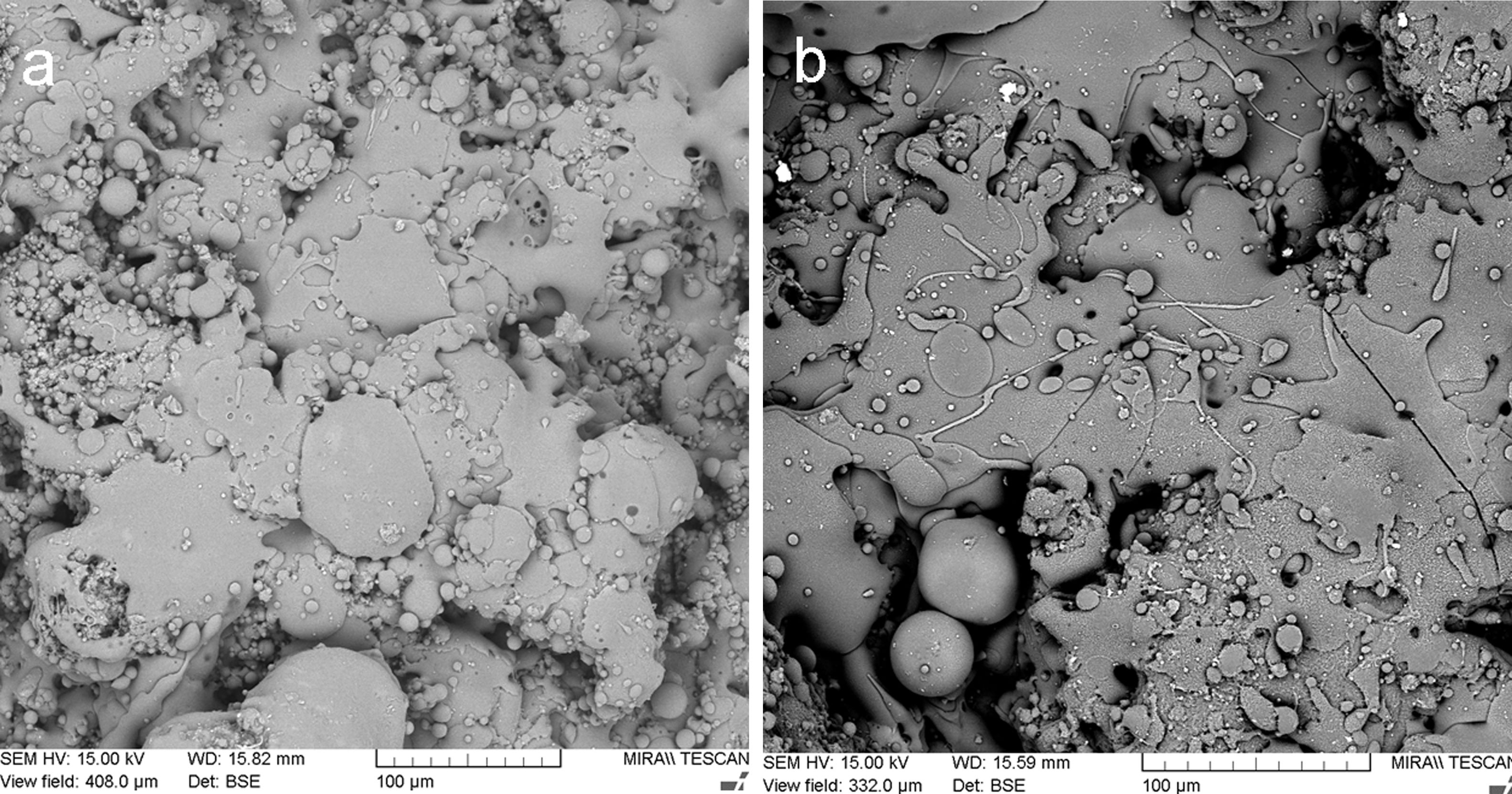
Fig. 4 shows a coating cross section and Fig. 5 the surface for KP and MK coatings. Both coatings exhibited significant clustering of pores. Besides that, they exhibited imperfections on inter-splat boundaries and also cracks (MK more pronounced cracks than KP). In comparison with the durability of conventionally sprayed dense “bulk-like” coatings, the microstructure of both actual coatings was adequate for gaining much lower thermal conduction. The “tail” in the particle size distribution at about 1μm volumetric fraction, c.f. Figs. 1 and 2, was due to the fine particles attached to the splat surfaces of both KP and MK, Figs. 4 and 5.
 Micrograph of the KP sprayed coatings, cross section. (b) Micrograph of the MK sprayed coatings, cross section.")
 Micrograph of the KP sprayed coatings, surface. (b) Micrograph of the MK sprayed coatings, surface.")
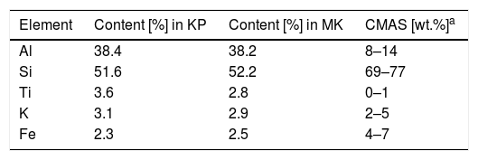
Based on the XRF results, Table 2, we could consider the chemical composition of both coating types nearly identical. Surface roughness of the KP coating was Ra=19.5±1.1μm, MK: Ra=26.0±2.1μm. This parameter was reported in literature for plasma sprayed mullite Al6Si2O13 with the value of 14μm [20], but mullite is typically more compact powder and therefore forms a smoother coating surface.
Microhardness on a KP polished cross section was HVm=9.45±2.65GPa at a 0.5N load, whereas the MK coating was harder (11.44±3.10GPa). The reported Vickers hardness varied from 1 to 4GPa at a 10N load depending of the sintering temperature [21], elsewhere reported as 2–7GPa depending on the sintering temperature (load not reported) [22]. Microhardness of flame sprayed mullite was reported to be about 7GPa [23]. Microhardness between 6 and 7GPa was reported for a mullite coating sprayed by plasma with gas stabilization [24]. Preheating of substrates to 700°C was applied to increase the microhardness from 7.1GPa (non-preheated) to 13.0GPa [25]. Microhardness of mullite coating formed from andalusite Al2SiO5 feedstock was about 6.5GPa [26] (Table 3).
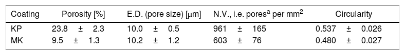
Porosity based on the image analysis (IA) results is summarized in Table 4. KP is much more porous compared to MK, whereas the size of pores is similar for KP and MK. The number of pores per square millimeter is 50% higher for KP. Circularity of pores is very slightly higher for KP. Summary of this quantification is that both coatings exhibit pores with approximately the same character, but KP in a markedly higher quantity. Porosity 7.8% was measured by image analysis on a mullite coating sprayed with equipment very similar to the actual experiments [27]. Porosity between 6 and 9% was reported (based on IA) on mullite coating sprayed by plasma with gas stabilization [24]. Porosity of a mullite coating formed from andalusite feedstock was about 6% [26]. Also, the actual KP coating exhibited extraordinarily high porosity whereas MK is in frame expected for similar sprayed materials.
Image analysis results of plasma sprayed KP and MK coatings.
| Coating | Porosity [%] | E.D. (pore size) [μm] | N.V., i.e. poresa per mm2 | Circularity |
|---|---|---|---|---|
| KP | 23.8±2.3 | 10.0±0.5 | 961±165 | 0.537±0.026 |
| MK | 9.5±1.3 | 10.2±1.2 | 603±76 | 0.480±0.027 |
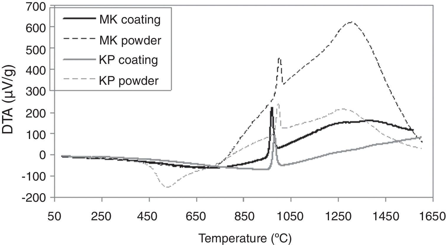
Differential thermal analysis results are depicted in Fig. 6. Endothermic peak on the curve of the starting KP powder with onset at 400°C signalizes dehydroxylation of kaolinite and formation of metakaolinite, which ends at 650°C, in concordance with other publications [28,29]. Hence, the temperature ensuring calcination of the starting powder was set as high as 700°C at the powder thermal treatment before spraying (that led to formation of MK powder from the starting KP powder). Crystallization of mullite occurred before 1000°C in the case of powders as well as coatings. Other authors specified this range to be 980–992°C [28]. A spinel type aluminosilicate (SAS) formation at about 980°C was mentioned in another work [18], or in the case of plasma sprayed deposit at 961±4°C [30]. A wide exothermic peak in the temperature range 1200–1300°C corresponds to the mullite formation from SAS [18]. In the KP coating, this peak was missing and thus this fact correlates to the absence of mullite detected by XRD, which agrees also with another paper dealing with plasma spraying of kaolinite flakes [30]. In case of KP powder, we stopped heating at about 1050°C to extract samples for XRD and resolve if the conversion to mullite is direct or indirect with intermediate SAS phase. The analysis of the pattern showed 28% of crystalline material and from this proportion, 16% was SAS (the rest: mullite 41%, quartz 27% and muscovite 15%). According to the character of CTE curves, KP coating exhibited this intermediate transformation as well, whereas MK not. Please consider that only a part of the material followed this “two step” transformation, whereas high majority transformed directly.
.")
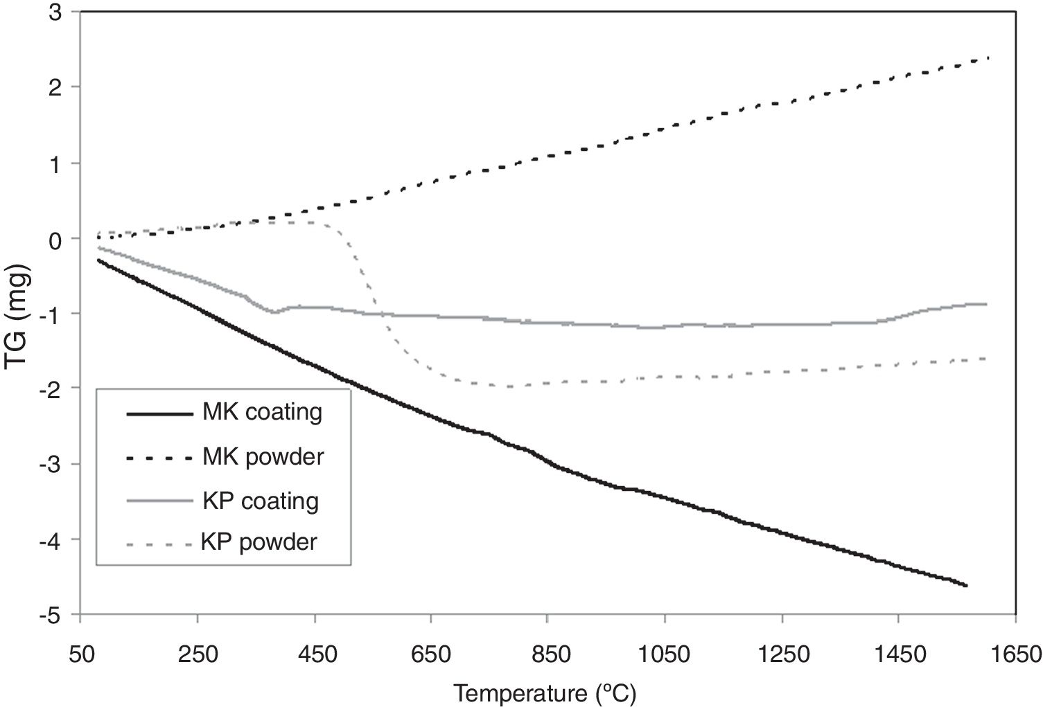
TG curves are presented in Fig. 7. KP powder lost weight markedly because of the dehydroxylation of kaolinite and formation of metakaolinite, which ends at 650°C. Above 650°C, the weight is constant. The weight of KP coating drops firstly because of continual loss of water (probably adsorbed water), and above 500°C, it is nearly constant.
.")
MK powder increased its weight continuously whereas MK powder lost its weight continuously. This is, because they differ during the dehydroxylation quantitatively.
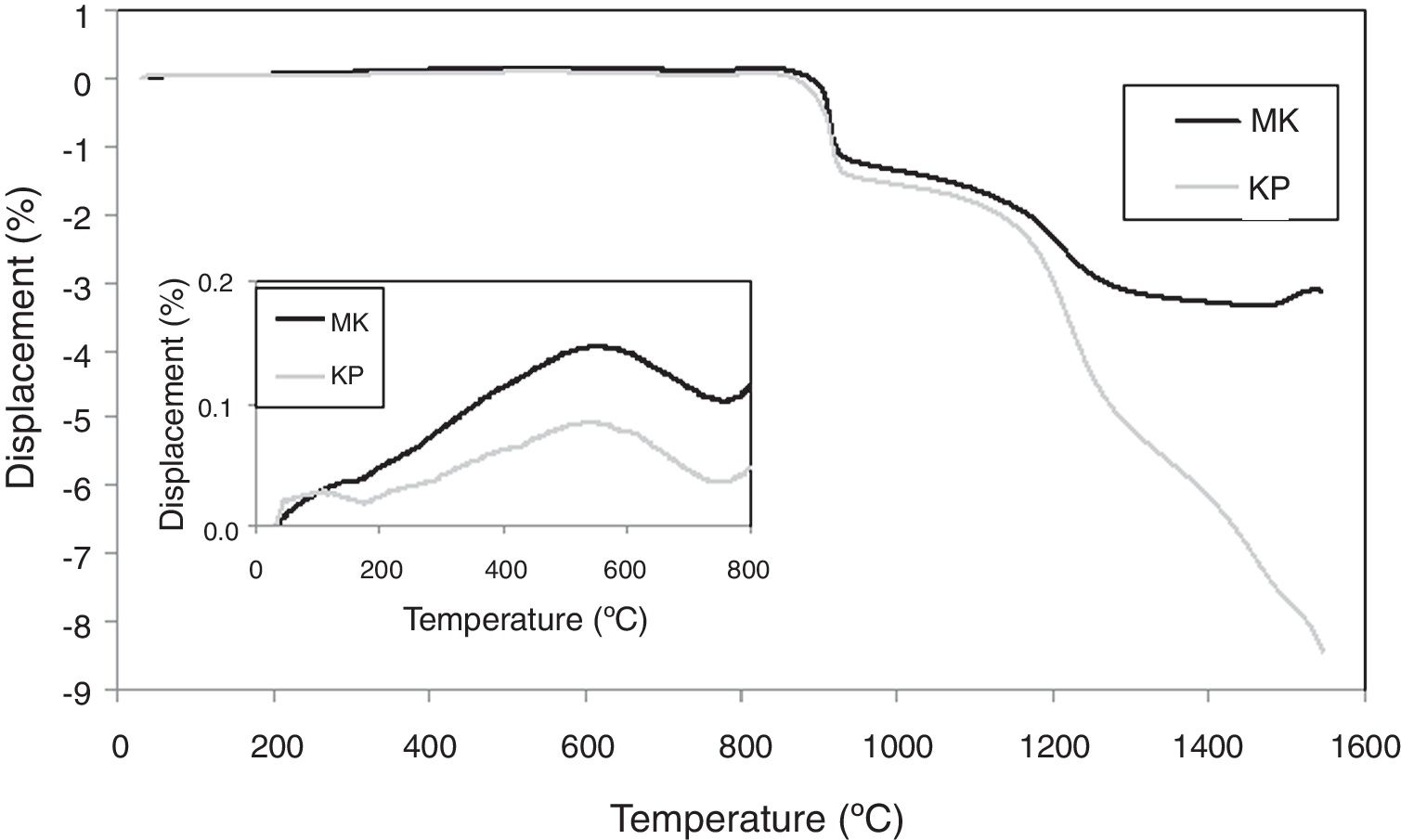
Curves of thermal expansion are displayed in Fig. 8. The values of the linear coefficient of thermal expansion (CTE) were calculated for the interval from 30 to 850°C and this parameter has a value of 0.6×10⁻⁶/°C for the KP coating and 1.5×10⁻⁶/°C for the MK coating, respectively. Plasma sprayed mullite had typically higher thermal expansion at elevated temperatures, 3.8×10⁻⁶/°C [31]. Values at R.T. (i.e. 9.4×10⁻⁶/°C for KP and 9.3×10⁻⁶/°C for MK, respectively) were higher than typical values of oxide ceramics and are much closer to metallic materials often serving as substrates, as for example stainless steel with CTE 15.5×10⁻⁶/°C. The constituent materials had following CTE: alumina 8.3–9.0, silica 9.0–14.0 and mullite 4.5–5.7 (all ×10−6/°C). Logically, the values of KP and MK were in between, MK slightly higher, because it contained slightly more silica.

The inset in Fig. 8 showed a peak on the displacement curve at about 600°C. In concordance with [32,33], this phenomenon corresponded to α-quartz to β-quartz inversion and was more pronounced in MK, richer in SiO2 than KP.
During sintering, the CTE above sintering temperature, about 850°C, was also negative [34], (i.e. the material shortened). So, we can summarize that CTE of our coatings were high at R.T. and decreased at high temperatures.
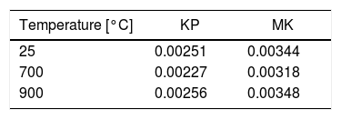
Thermal diffusivity of plasma sprayed KP and MK coatings is listed in Table 5. Near 800°C, various ceramics change the thermal diffusivity behavior from a drop to a rise with the growing temperature [35–37]. Behavior of both types of our coatings was similar, Table 5. Kaolinite had lower values of diffusivity than metakaolinite because of presence of more pores and less pronounced sintering. The values of thermal diffusivity as well as their evolution with temperature were very similar to our coating sprayed from natural ZrSiO4 (unpublished results).
Phase composition and reactivity with CMASReactivity of the coating with calcium-magnesium-aluminum silicate (CMAS) powder was tested. The CMAS powder was Ultrafine Test Dust “Arizona desert sand” produced by Powder Technology (Arden Hills, MN, USA). Its chemical composition provided by the producer is in the last column of Table 2. The dust powder was mixed with ethanol and applied on the coating surface by a brush. Then this sample was dried in air at room temperature for 3hours and subsequently annealed in air for dwell time of 4hours at 1150°C. The resulting phase components are summarized together with all other phase composition investigations in Table 6. “Annealed coating” means the same thermal procedure (4h at 1150°C) but without CMAS.
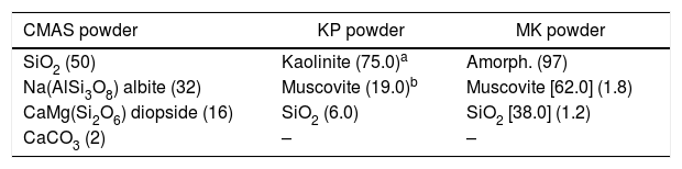
XRD phases – semiquantitative content (% of total), [% of crystalline only].
| CMAS powder | KP powder | MK powder |
|---|---|---|
| SiO2 (50) | Kaolinite (75.0)a | Amorph. (97) |
| Na(AlSi3O8) albite (32) | Muscovite (19.0)b | Muscovite [62.0] (1.8) |
| CaMg(Si2O6) diopside (16) | SiO2 (6.0) | SiO2 [38.0] (1.2) |
| CaCO3 (2) | – | – |
| KP coating | KP coating annealed | KP coating annealed with CMAS |
|---|---|---|
| Amorph. (97) | Amorph. (38) | Amorph. (47) |
| Gamma Al2O3 [85.5] (2.4) | Al6Si2O13 mullite [97.0](60) | Al6Si2O13 mullite [51.0] (27) |
| SiO2 [15.5] (0.6) | SiO2 [3.0] (2) | SiO2 [28.0] (15) |
| (Ca0.64Na0.32) (Al1.775Si2.275)O8 labradorite [21.0] (11) |
| MK coating | MK coating annealed | MK coating ann. with CMAS |
|---|---|---|
| Amorph. (95) | Amorph. (39) | Amorph. (42) |
| SiO2 [42.0] (2.3) | Al6Si2O13 mullite [97.5] (60) | Al6Si2O13 mullite [42.5] (25) |
| Al6Si2O13 mullite [30.0] (1.5) | SiO2 [2.5] (2) | (Ca0.64Na0.32) (Al1.775Si2.275)O8 labradorite [31.0] (18) |
| Gamma Al2O3 [28.0] (1.2) | – | SiO2 [25.5] (15) |
KAl2(AlSi3O10)(F,OH)2, i.e. transparent mica mineral.
CMAS composition is based on literature [19].
Fully crystalline kaolinite (KP) powder was nearly completely amorphized by the plasma spray process. Metakaolinite (MK) powder is considered amorphous, because the metakaolinite mineral does not exhibit diffracting peaks [20,38,39]. Chemically, more simple phases as alumina, mullite and SiO2 appeared after spraying instead of muscovite, which is a hydrated phase. Elements like K and F are, expectably, absent in coatings because of their volatility.
Surface of the coating obtained a brown “glaze” after annealing with CMAS. The phase present in both coatings annealed with CMAS, (Ca0.64Na0.32)(Al1.775Si2.275)O8, is mineralogically called labradorite – a feldspathic mineral, and it originated from albite, diopside and CaCO3. This means that. CaO remained, while CO2 was vaporized from CMAS in reactions with Al and Si from the as-sprayed coating. Both coatings annealed with CMAS became richer in silica compared to the annealed coatings. In conclusion, CMAS has detrimental effect on the KP coating, because labradorite is a less thermally stable phase compared to mullite constituting the crystalline fraction of the as-sprayed coatings.
Kaolinite dehydroxylation occurs through a three-dimensional diffusion process with formation of an amorphous product identified as metakaolinite (Al2Si2O5). This process is completed above 650°C. Metakaolinite remains short-range ordered at least to 980°C. Formation of mullite at 995–998°C, i.e. primary mullite, side by side with a cubic phase, Si–Al spinel (SAS), and amorphous silica-rich component at around 983°C, was confirmed, namely for both powders. From 1136°C, growth of mullite crystals occurs, and at T>1200°C, crystallization of high temperature cristobalite (SiO2) from an Si-rich amorphous phase takes place. Additionally, in the Si-rich amorphous component formed at kaolinite-muscovite interfaces. Secondary mullite crystallization occurs at 1300°C [28]. At a higher heating rate (over 1°C/min), delamination (destruction of kaolinite sheet structure) prevails over the dehydroxylation [29], and this is the case of plasma spraying, but also the case of thermal re-forming of KP into MK.
SummaryKaolinite with structurally bonded water and metakaolinite without it were successfully plasma sprayed. Metakaolinite powder was obtained by thermal treatment of natural raw kaolinite. The coatings were rather porous, mainly the kaolinite-based ones, and composed predominantly of amorphous material. Metakaolinite coating was less porous and harder. Muscovite phase, found in the powder, disappeared after spraying, while new phases were present – alumina in the kaolinite coating and moreover mullite in the metakaolinite coating. Annealing for 4h at 1150°C increased the proportion of crystalline material and increased the mullite content. After interaction with Si-rich CMAS dust, another “exotic” phase – labradorite – appeared, but mullite and silica remained the most important components.
Authors thank to J. Medricky, IPP ASCR, for the powder size measurements.
