


Mechanism of MFI film growth from seed crystals and evolution of defects during the film growth were investigated. The hydrothermal growth of colloidal silicalite-1 crystals of 50nm on silicon substrate was used to reveal the MFI film formation mechanism at different time intervals using high resolution-transmission electron microscopy (HR-TEM) and extreme high resolution-scanning electron microscopy (XHR-SEM). It was found that the MFI seeds started to grow in the early stages of hydrothermal treatment from 50nm to 75nm in size and connect to the crystals in the vicinity, showing the onset of film formation. The film growth mechanism was led by the sub-colloidal particles in the synthesis solution arriving at the crystal surfaces contributing to the film growth. A continuous film with a thickness of 100nm was formed after 12h of hydrothermal treatment containing pinhole defects. Pinhole defects disappeared after 24h of hydrothermal treatment with a film thickness of 200nm and grain boundaries thickness of 2nm were formed. Furthermore, mesoporous defects were found in the grains of the film, which appeared due to the film growth by sub-colloidal particles of synthesis solution. The growth rate of the MFI film was calculated to 0.007 (μm/h) and compared with the crystal growth inside the synthesis solution.
Se investigó el mecanismo de crecimiento de películas de MFI a partir de cristales semilla y la evolución de los defectos durante el crecimiento de dichas películas. La síntesis hidrotérmica a partir de cristales coloidales de silicalita-1 de 50 nm sobre sustrato de silicio se utilizó para revelar el mecanismo de formación de la película de MFI en diferentes intervalos de tiempo, utilizando microscopía electrónica de transmisión de alta resolución (HR-TEM) y microscopía electrónica de barrido de extrema alta resolución (XHR-SEM). Se observó que las semillas de MFI comenzaron a crecer en las primeras etapas del tratamiento hidrotérmico de 50 a 75 nm de tamaño y se conectaron a los cristales en las cercanías, evidenciando el inicio de la formación de la película. El mecanismo de crecimiento fue dirigido por las partículas subcoloidales en la solución de síntesis que llegaron a las superficies de los cristales, contribuyendo al crecimiento de la película. Se formó una película continua con un espesor de 100 nm después de 12 h de tratamiento hidrotérmico que contenía orificios. Estos desaparecieron después de 24 h de este mismo tratamiento, habiendo alcanzado un espesor de película de 200 nm, y se formaron límites de grano de 2 nm. Además, se encontraron defectos mesoporosos que aparecieron debido al crecimiento de la película a partir de partículas subcoloidales presentes en la solución de síntesis. La tasa de crecimiento de la película de MFI se calculó en 0,007 (μm/h) y se comparó con el crecimiento de cristales dentro de la solución de síntesis.
Zeolites have crystal structures with uniform molecular sized pores [1–3], and are widely used as membranes [4–6], catalysts [7,8], adsorbents and ion exchangers [9]. The favourability of zeolites in chemical applications is due to their framework, shape [6,10], and pore size [11,12].
It is essential to have defect-free zeolites. Optimising the growth mechanism can significantly help to eliminate defects [13]. Understanding the zeolite growth mechanism has been investigated by researchers to optimise the synthesis procedure [14,15]. Different techniques such as dynamic light scattering (DLS) [16], nuclear magnetic resonance (NMR) [17], small-angle X-ray scattering (SAXS) [18], and high-resolution transmission electron microscopy (HRTEM) [17,19,20] have been used to study the nucleation and crystal growth of zeolites. Silicalite-1 is one of the most popular zeolites for nucleation investigations due to the possibility of synthesis from simple synthesis mixtures and ease of analysis [15]. Therefore, growth investigations, to design and tailor zeolite crystals and membranes [21], can be carried out using silicalite-1.
Silicalite-1 with straight channels (5.3×5.6Å) as well as zigzag channels is a kind of MFI zeolite with a Si/Al ratio of more than 200 [22]. Silicalite-1 films can be synthesised on a substrate with different techniques such as microwave synthesis [23], free-seeding synthesis [24] and secondary growth using seeds [25]. The synthesis of silicalite-1 film from seed crystals has shown better control over the uniformity and quality of the films [26–29]. However, the details of the growth mechanisms, evolution of uniform film with lower concentration of microstructural defects, are not researched. A better understanding of film formation from seeding may help with a rational methodology for optimising the zeolite film synthesis by obtaining a fine-control of grain boundary structure, film thickness and, consequently, a better control over the amount of pinholes, cracks and other types of defects [29].
In general, reducing the concentration of defects is critical for the performance and stability of the high-silica zeolite films [30]. The intracrystalline defect is one of the most well-known defects in zeolite crystals, originating from broken Si-O-Si bonds resulting in micropore defects and silanol groups [31]. Dissolution of zeolite crystals, e.g. dissolution due to the rinsing with improper chemicals, may also lead to defects [32]. The intercrystalline defects and rinsing-induced defects influence the mechanical and thermal stability of the zeolite films [32]. The large defects such as pinholes and open grain boundaries appear due to the lack of a homogeneous seed layer [33] and lack of optimised conditions of film growing [13]. These large defects act as alternative transport pathways with a diameter larger than zeolite pores and influence the separation performance [34].
Persson et al. [35] investigated colloidal particles of TPA-silicalite-1 in a clear solution. A clear solution could help to estimate the formed crystals’ size by gathering them at each step. In addition, they could monitor the crystallinity of the clear solution at each step. Finally, they reported a linear crystal size increase by time [35]. Schoeman et al. [36] claimed that TPA-silicate precursor solution contained sub-colloidal particles after ageing at room temperature. The particles had an average size of 3.8nm. This meant that the solution contained amorphous nano-particles before thermal treatment, which has also been reported by other researchers [37,38]. The Tsapatsis group [39] investigated the formation of nanoparticle crystals of silicalite-1 zeolite at room temperature by ageing of pure silica suspensions. It was suggested that zeolite growth occurred through nanoparticles’ aggregation inside the solution. They claimed that the aggregate-like morphology of the silicalite-1 crystals was due to the nanoparticles participating in the nucleation and crystallisation processes.
Bonilla et al. [40] investigated the growth of MFI films. They found the film thickness increased with increasing the average grain size. However, the growth of the adjacent grains with different velocities and orientations resulted in the undesired formation of voids (pinholes) and defects in the film. In the authors’ recent publication [41], the micropore defects of the MFI membrane were characterised as open-grain boundaries. The foregoing was confirmed by employing high-resolution scanning electron microscopy. Camblor et al. [42] synthesised aluminosilicate zeolite beta in fluoride media at near neutral pH. They found broken Si–O bonds in the lattice lead to an increase in the mesoporosity on zeolite crystals.
In the present study, we have investigated the mechanisms of growth of MFI seed crystals stage by stage on silicon support in the synthesis solution to grow a uniform zeolite MFI film. We have employed extreme high-resolution SEM and TEM to show the growth of the MFI seed crystals to form MFI film and the evolution of defects of different length scales, micro-meso-macroporous defects. As one of the main concerns in the literature, the evolution of micro-meso and macro defects in the MFI film during film growth has been reported. More importantly, it has been investigated if it is possible to avoid formation of defects like mesoporosity in the MFI films by optimisation of the film growth parameters. The growth rate of MFI film has been evaluated and compared with the growth of MFI crystals to show the consistency of the arguments.
ExperimentsMaterialsTetraethoxysilane (TEOS, >98%, Merck), tetrapropylammonium hydroxide (TPAOH, 40%, Sigma), tetraethylammoniumhydroxide (TEAOH, 40%, Sigma), ammonia (99.98% sigma), cationic polymer (Redifloc 4150, Eka Chemicals AB, Sweden), acetone (99.9%, sigma), ethanol (99.9%, sigma) and hydroxypropyl cellulose (sigma), were the materials used in this work.
Seed preparationColloidal silicalite-1 crystals with the size about 50nm were prepared by hydrothermal treatment at 50°C, while the molar composition of synthesis solution was 9TPAOH:25SiO2:360H2O:100EtOH similar to what was reported previously by our research group [43]. The solution was dispersed in water to make 1wt. % of seed solution and some ammonia was added to adjust the pH to around 8.5.
Particles and growing filmsIn order to make the synthesis solution, TEOS, TPAOH and water were mixed in a polypropylene bottle and placed on a shaker at room temperature for 24h to obtain a fully-hydrolysed clear synthesis solution [41,44]. The composition of the clear solution was 3TPAOH: 25SiO2: 1450H2O: 100EtOH. The synthesis solution was prepared for a variety of different aims.
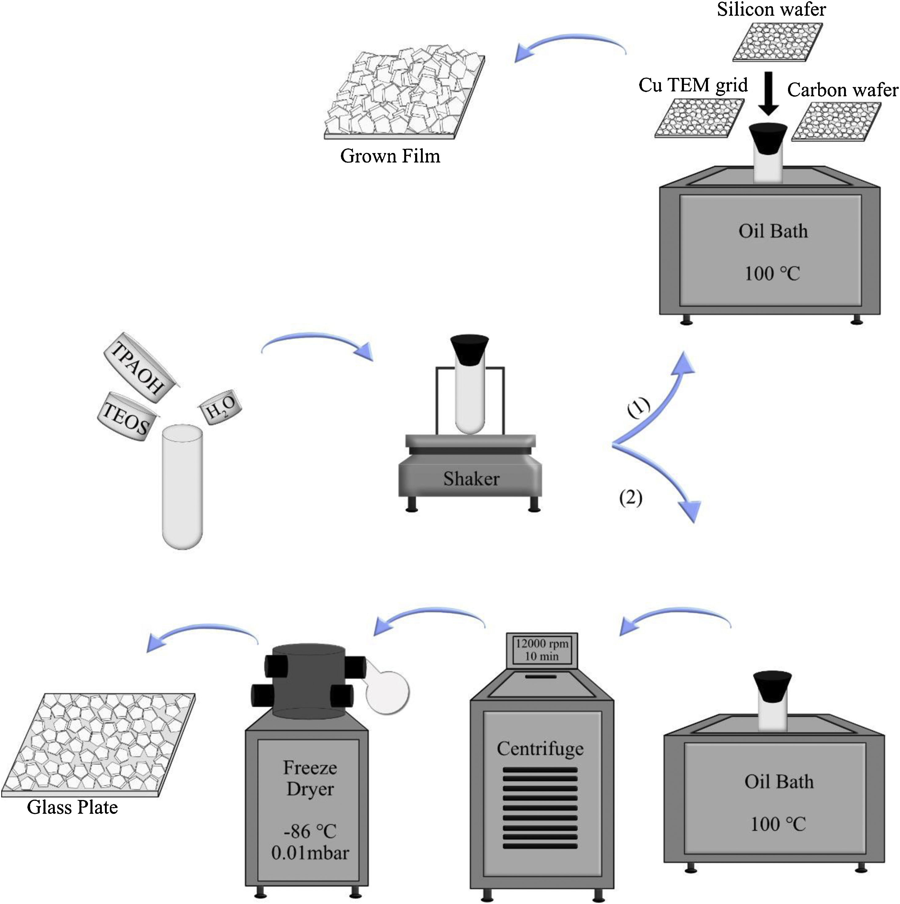
To investigate the film growth, the synthesis solution was used for growing film on substrates, such as silicon wafers, holey carbon films on Cu TEM grids, and amorphous carbon wafers (inert). To the regard of sample preparation, it was mandatory to use 3 different supports. When the case was the investigation of film growth by SEM, silicon wafers could be proper to use. For TEM characterisation, Cu TEM grids had to be used. Carbon wafers could help to see the bottom side of the film by detaching from the support due to the tensions. The supports were rinsed 5 times in 0.1M NH3, which was passed through a 0.1μm pore filter. Subsequently, they were treated with a cationic polymer solution and passed through a 0.8μm pore filter for 10min, which made the support surface positively charged. The supports were rinsed again in ammonia (for the same times and method), and seeded with seed solution (passed through a 0.2μm pore filter) for 10min and again rinsed 5 times in ammonia [43]. All substrates were mounted on Teflon holders, submerged in a synthesis solution in PE tubes and heated in an oil bath at 100°C under closed reflux conditions, see Scheme 1. The growth times of MFI films were 2, 4, 6, 8, 12, 24, 36 and 120h.
In the second part, the synthesis solution was transferred to PE tubes and heated in an oil bath under closed reflux conditions. The synthesis solution was treated in 11 different time durations at 100°C (denoted SS, synthesis time, i.e., SS100 represents the hydrolysed synthesis solution treated for 100h). After hydrothermal treatment, the tubes were immediately transferred to an ice bath to decrease their temperature. Then, the solution was freeze-dried in order to provide powder for each sample. This was done to limit the aggregation of crystals [45]. For extraction of the crystals from the synthesis solution, they were treated in 5 different time durations. After heating, all samples (SS24, SS36, SS48, SS62 and SS88) were washed by centrifuging at 12,000rpm for 10min. Afterwards, particles were dispersed in distilled water, and the washing procedure was repeated 6 times for each sample. Then, the solution was freeze-dried (temperature of −86°C and vacuum pressure of 0.010mBar) to provide powder for each sample. As the last step, to assemble a monolayer of the samples, polymer hydroxypropyl cellulose (HPC) was dissolved in ethanol to obtain a 2wt. % solution. A spin-coater was used to deposit very thin films of HPC on glass plates. The glass plates were put under sonication in acetone and ethanol for 5min, followed by drying. One drop of solution was enough to cover the whole area of the glass plate, and the film deposition was performed for approximately 20s with a spinning rate of 2500rpm. The polymer layers were kept at 105°C for 1h to be dried. Assembling monolayers of oriented crystals on the plate was done by rubbing the powders using a nitrile gloved finger at relative humidity of RH=60%. After rubbing, clean soft cotton was used to remove the physisorbed multilayers by gentle wiping. Finally, in order to remove the polymer layers between zeolite crystals and glass plates, the plates were calcined at 550°C for 5h. More elaboration is provided in Scheme 1.
Ammonia rinsing investigation and monolayer coating from the extracted crystals from the synthesis solution (2).")
Three films grown for 36h were rinsed with ammonia to investigate the ammonia effects on them. Three methods were utilised for rinsing; no rinsing, normal, and harsh rinsing. In normal rinsing, the films were rinsed 5 times with 0.1M ammonia for a few seconds followed by 3 times rinsing with water, and then 1 time rinsing with acetone. In harsh rinsing, the films were rinsed 1 time with 1M ammonia for 48h, and then 3 times with water, and finally 1 time with acetone, as was done in normal rinsing.
Image analysisMATLAB (license no. 842635) software was used in order to analyse the particle size distribution and find the largest particles. A total of 200 SEM images of each sample were analysed to estimate the size of about 1000–1500 particles.
CharacterisationXRDA Panalytical Empyrean diffractometer was employed in order to record X-ray diffraction (XRD) data. The instrument was run in Bragg–Brentano geometry. Here, 2θ range 10°–40° was selected to collect the XRD data using a Cu-tube operated at an accelerating voltage of 45kV and a current of 40mA. The intensity of 5 reflections in the 2θ range 22.5° to 25° were determined. This was done by fitting a symmetric pseudo Voigt profile to the experimental data, as has previously been reported in our group [8]. For relative crystallinity estimation, the sum of intensities of the 5 reflections for each sample was calculated. Since SS100 displayed the highest sum of intensities, it was taken as a reference with 100% crystallinity, and the crystallinity of the other samples was calculated.
XHR-SEMXHR-SEM (extreme high resolution-scanning electron microscopy) was utilised to resolve the three-dimensional microstructure of MFI films, using FEI Magellan 400 field emission SEM.
HR-TEMHigh-resolution transmission electron microscopy was run by JEM-2100F (JEOL Ltd.) at 200kV. In order to prepare the TEM samples, self-supported zeolite films grown on amorphous carbon wafers were embedded in LR white resin. In order to clean the top surface of the film, thin sections of 60nm were cut with a diamond knife and the resin was removed by plasma cleaning.
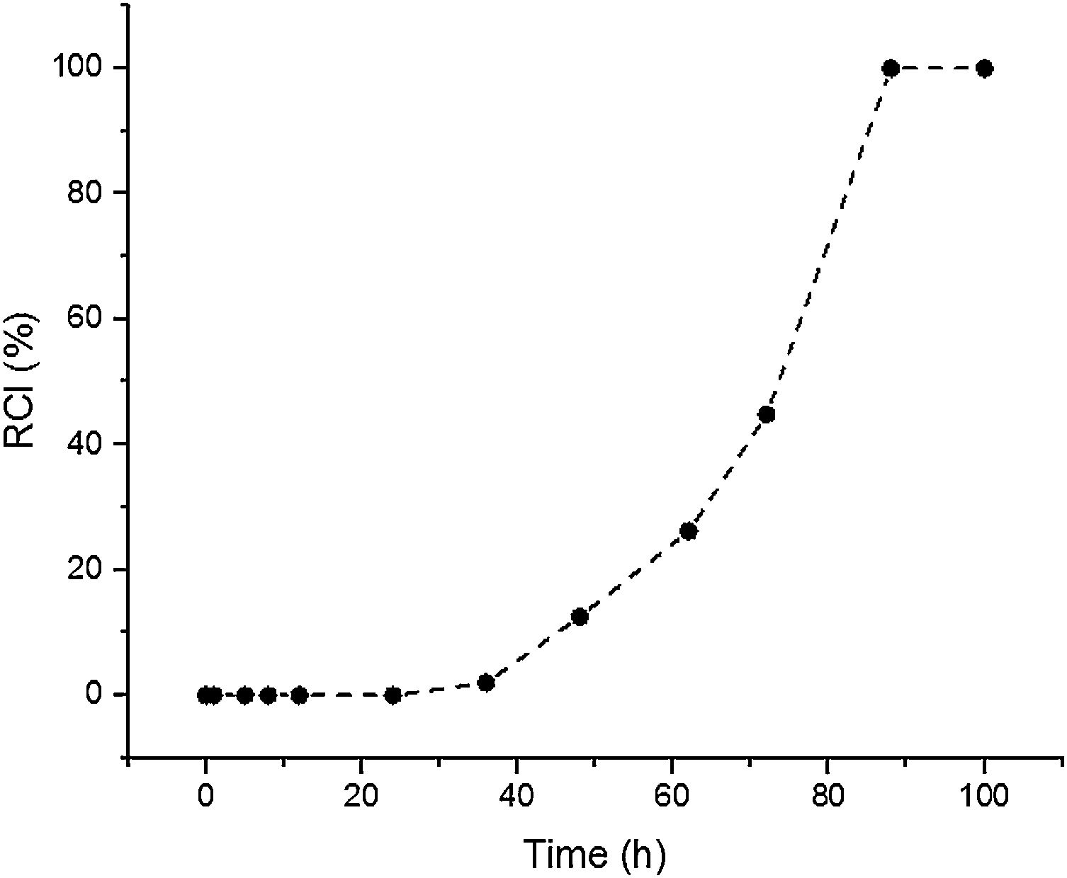
Results and discussionSynthesis solution investigationThe crystallisation of ZSM-5 with hydrothermal treatment in the synthesis solution was monitored by XRD. The effect of hydrothermal treatment time on the relative crystallinity of ZSM-5 in the synthesis solution at 100°C (11 specimens) is presented, Fig. 1. ZSM-5 crystals are not detected until 24h, which is counted as the incubation period. Between 24 to 88h, the relative crystallinity increased from 0% to about 99%. According to the literature [46,47], the crystals nucleate and grow at the expense of the amorphous phase. The increase of the relative crystallinity after 88h was negligible, probably due to the insufficient supply of nutrients, indicating that the crystals grow at the expense of less stable crystals, known as Ostwald ripening [48]. Similar observations have been reported in the literature [49,50] where the amorphous phase was detected at the start of the hydrothermal treatment and then the relative crystallinity increased and became constant with time. Therefore, the synthesis time between the nucleation of crystals (after 24h) to the end of amorphous phase (after 88h) could be a good domain to investigate the crystal growth kinetics.

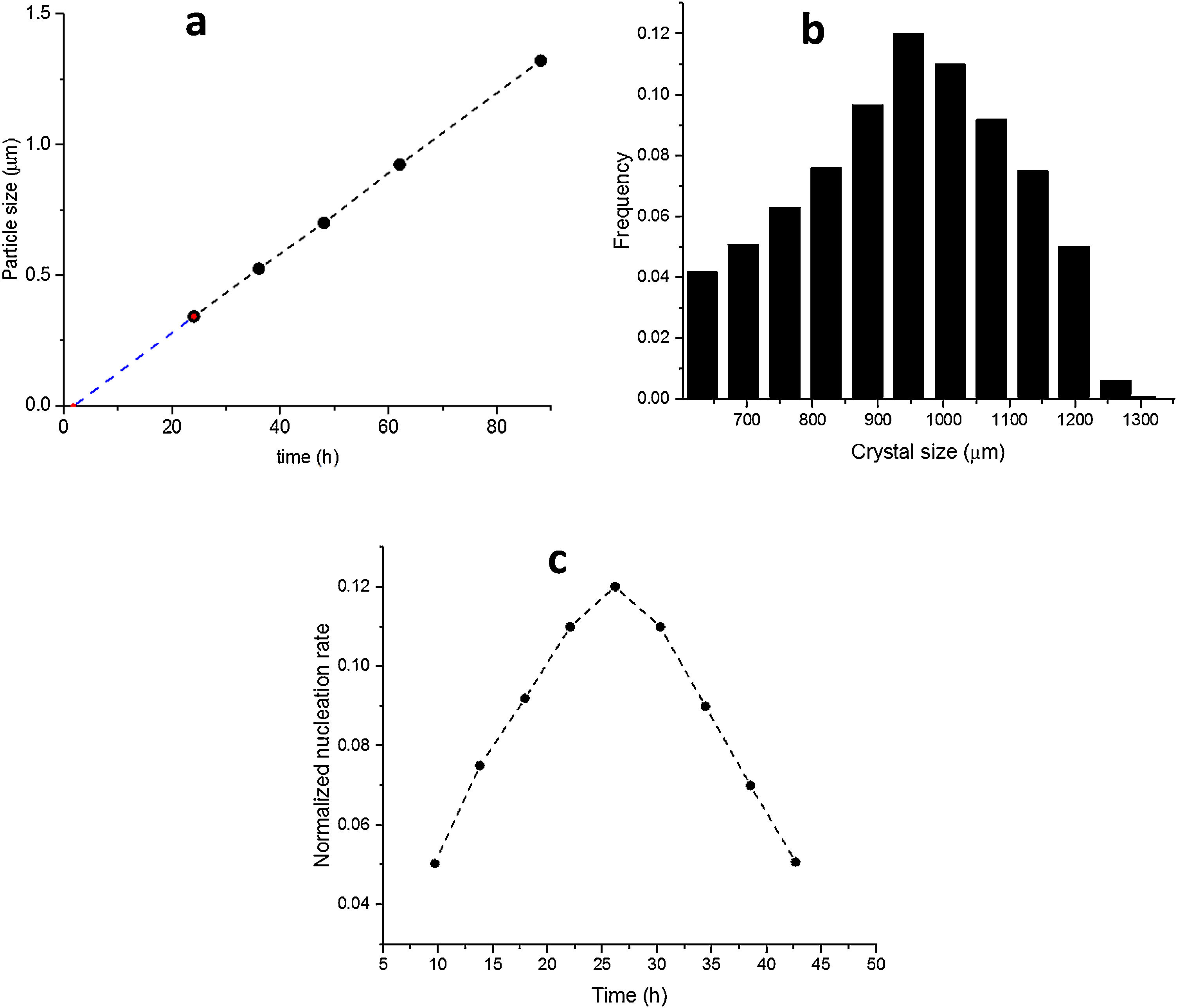
The SS24, SS36, SS48, SS62 and SS88 crystals were chosen to estimate the growth rate. All the crystals were washed and extracted from the synthesis solutions and coated on the glass plate to investigate the size, see Figure 1.s.Fig. 2a presents the largest crystal size for each synthesis, extracted by MATLAB, as a function of time. The achieved data were drawn and then fitted to a line then continued to find the intersecting point with the X-axis. This was done to find when the first crystal was nucleated. So, the first crystal formed after 1.76h and the growth rate calculated was 0.015 (μm/h) at 100°C.
 Size of the largest ZSM-5 crystal for each synthesis time, (b) Final distribution in length of ZSM-5 crystals after 88h (S88), (c) Normalised nucleation rate (S88).")
Fig. 2b shows the crystal size distribution for S88 extracted by MATLAB from 600 to 1300μm. By assuming a constant crystal growth independent of the crystal size, the normalised nucleation rate can be derived, see Fig. 2c. The nuclei were created more by time (during the crystal growth) and the maximum nucleation rate was around 24h. As the first statement, it was clear that enough nutrients were available in the synthesis solution to create nuclei until 88h treatment. Moreover, by considering first crystal formation before 2h, and also a continuous nucleation until 88h with a maximum rate around 24h, it is evident that the crystals were grown by consuming the amorphous particles in the synthesis solution (and not by consuming the small crystals). This could be introduced as the crystal growth mechanism within the film on a seeded substrate. To give a fully clear mechanism of the contribution, further investigation on the film (as a combination of different crystals) growth was needed.
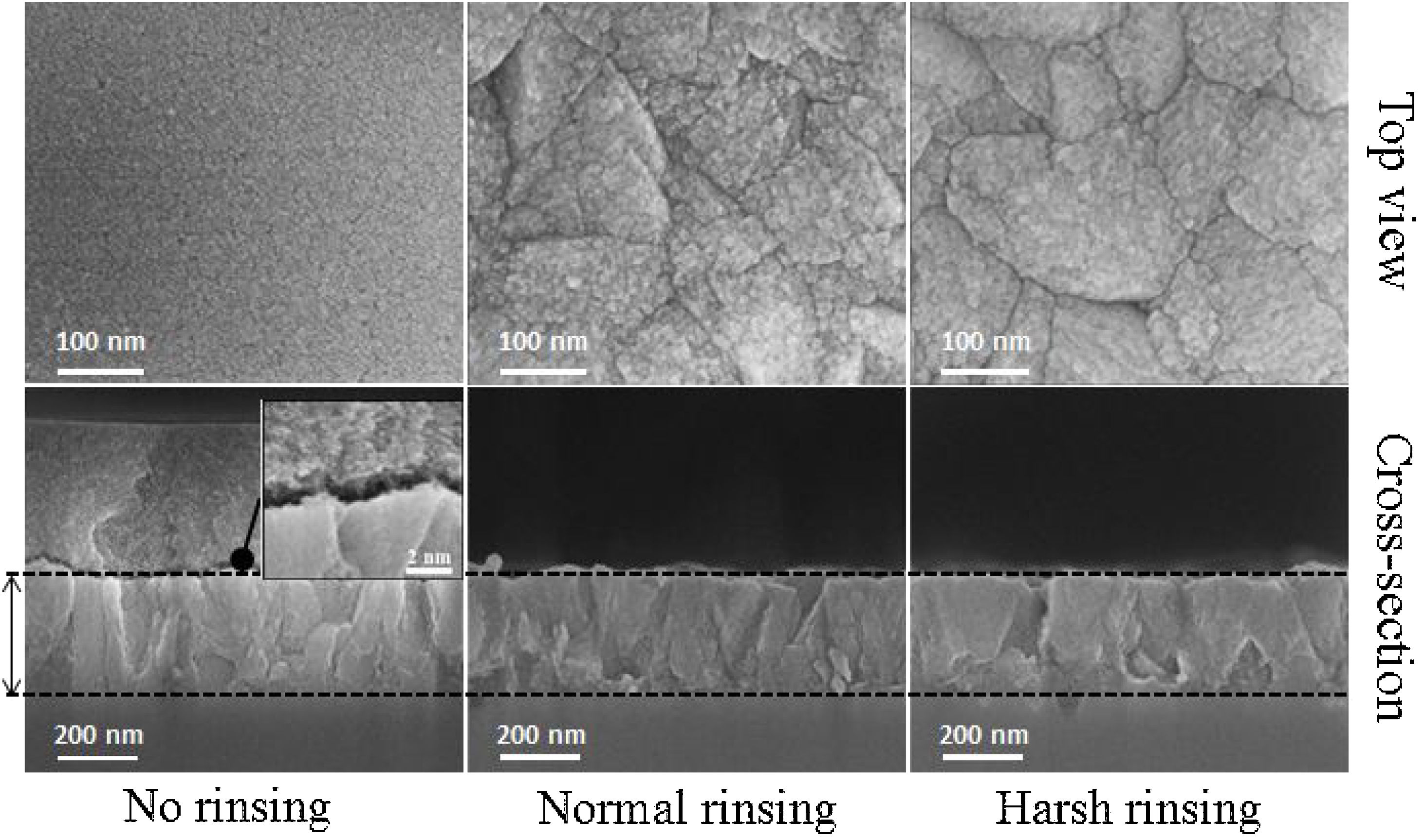
Film formationFig. 3 provides SEM micrographs of fully grown films. The film before rinsing shows that the nanoparticles of 3–4nm in size precipitate on the film [36]. As the first evidence, nanoparticles precipitation on the film even after 72h of synthesis can be seen which can be related to the film growth. To investigate the film growth, it is important not to change the morphology of the crystals on the surface. On gentle and harsh rinsing, these nanoparticles detach from the surface. The harsh rinsing shows dissolution of the film surface while the surface of the crystals looks clearer with smoother morphology and the crystals are looked like a polished surface. On the other hand, the surface remains more uneven with more grain boundaries between the crystals in the case of normal rinsing showing there is no dissolution. The normal rinsing of the films after hydrothermal treatment was adopted for microstructural investigations.

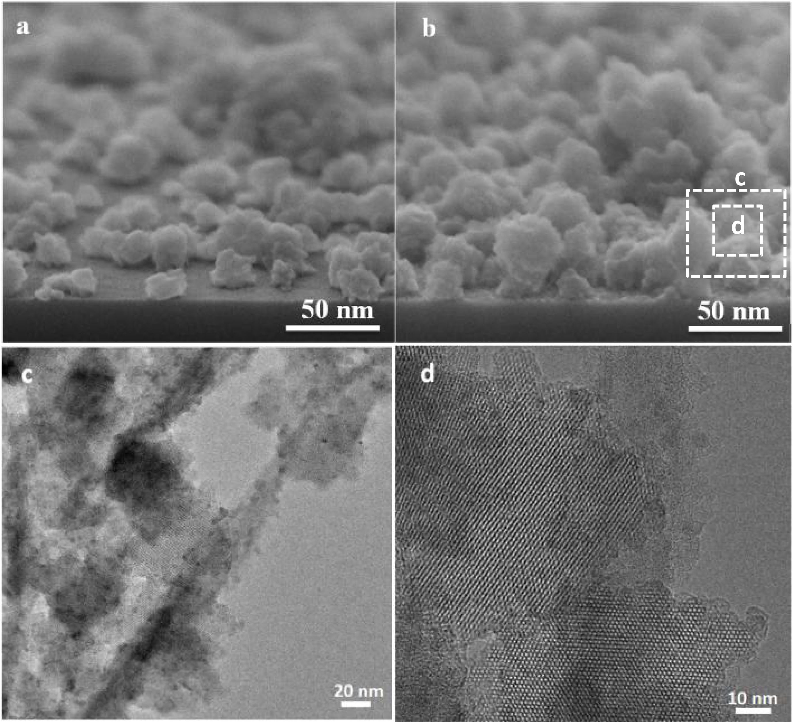
The seeded substrates were hydrothermally treated in the synthesis solution. Fig. 4 shows the SEM micrograph of the seeded silicon wafer (Fig. 4a) and seeded silicon wafer treated in synthesis solution for 2h (Fig. 4b). It can be seen (Fig. 4a) that the seeds are randomly oriented and distributed homogeneously on the substrate. After 2h of thermal treatment (Fig. 4b), the seeds were grown in average size from 50nm to 75nm, suggesting that the seeds had been growing in the synthesis solution which agrees with previous results in crystal formation. The created nano-asperities are visible on the surface of the growing crystals. Amorphous nanoparticles were observed on the crystals and substrate. The amorphous nanoparticles are the subcolloidal particles from the synthesis solution which attach on the crystal surface and could not detach on rinsing. The existence of the amorphous nanoparticles on the crystals after 2h of synthesis was confirmed by TEM of the grown seeds (Fig. 4c and d). These findings suggest that the hydrothermal growth of seeds has occurred in three steps: (I) formation of subcolloidal nanoparticles in the synthesis solution, (II) approach and attachment on the crystal surface, and (III) leading to the crystal growth which has been confirmed by TEM and SEM.
, after 2h of hydrothermal treatment (b), TEM micrographs after 2h hydrothermal treatment (c,d).")
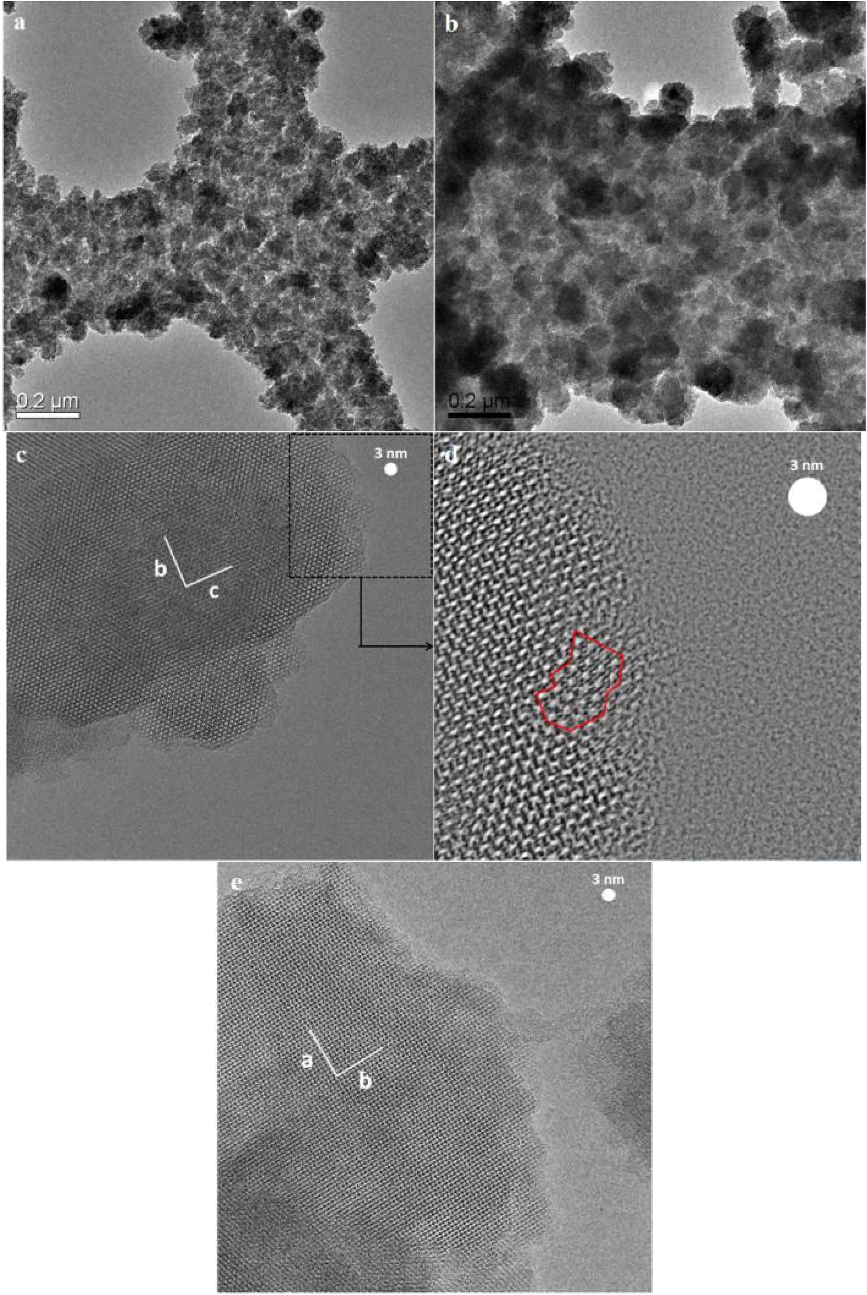
Fig. 5 shows the TEM micrographs of the seeds hydrothermally treated for 4h and 8h. The asperities formed on the seeds after 4h were crystalline (Fig. 5a) and few amorphous nanoparticles were observed on the crystals (Fig. 5b). The TEM micrograph of 8h treated seeds (Fig. 5c and d) showed a-oriented growth of the film with the presence of amorphous particles in Fig. 5e. Since, in any stage of the thermal treatment (even after 8h) the presence of nanoparticles on the surface of grown crystals were observed in the TEM micrographs in Fig. 5e. This confirms that the growth mechanism of the films is led by the attachment of nanoparticles (sub-colloidal particles) from the synthesis solution followed by their crystallisation and it is in line with the literature [51–53].
 and 8h (c,d,e) in the synthesis solution.")
In this part we have shown the film growth from the seeds stage by stage using to see the formation of each important parameter in non-defective film formation. The high-resolution SEM micrographs (top and side view) of seeded substrates hydrothermally treated for 2, 4 and 6h are presented in Fig. 6. It can be seen that, by increasing the synthesis time, the size of the seeds enlarged after each time interval and the seeds grow independently, both laterally and vertically with a limited increase in the thickness. The top view SEM micrographs reveal that the voids between the seeds become smaller and the intracrystalline growth leads to the formation of interconnections amongst the seeds. On further growth, the crystals merge with the surrounding crystals [54], and discontinuities appear in some parts of the substrate which is referred as pinhole (Fig. 6f) [55].
 and top view (right) SEM micrographs of seeded silicon wafers substrate after hydrothermal treatment for 2h (a,b), 4h (c,d) and 6h (e,f).")
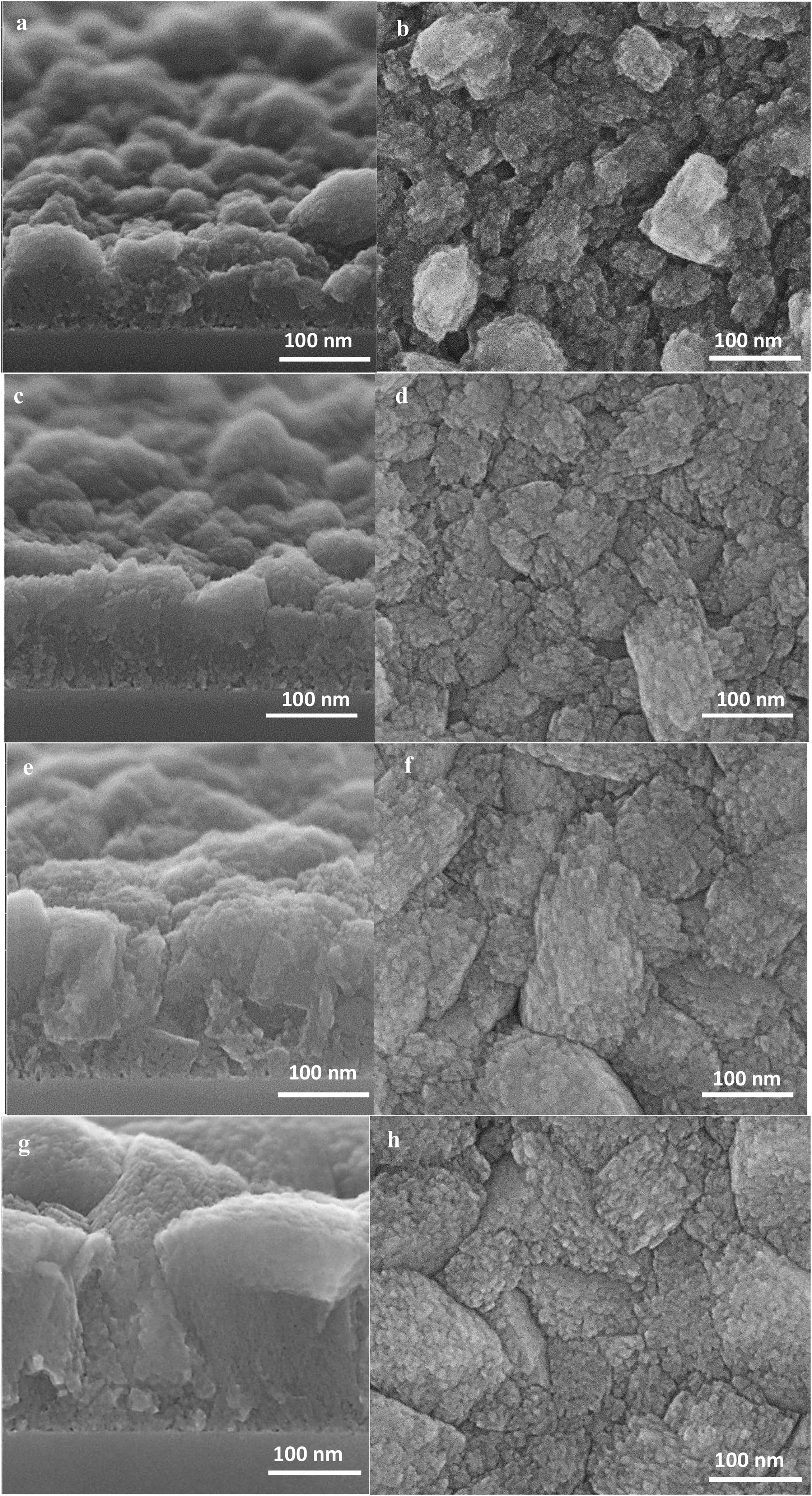
After 8h, the crystals’ growth continues and the pinholes have mostly disappeared, Fig. 7a and b. After 12h, the crystals formed grains and a continuous film with a thickness of about 100nm was formed, see Fig. 7(c and d). At this stage, the pinholes are not present, and the film represents the structure of an ideal as-synthesised zeolite film without intracrystalline gaps. It may be concluded that pinholes have disappeared as soon as a continuous film forms even the film is not fully developed, and cracks are still there.
 and top view (right) SEM images of seeded silicon wafers substrate after hydrothermal treatment for 8h (a,b), 12h (c,d), 24h (e,f) and 36h (g,h).")
At this stage of the hydrothermal treatment, the grain boundaries start to appear, which could be either open or closed [56]. The grain boundaries propagate from the substrate to the film top surface, due to the crystal growth and enlargement from the substrate to the top [34].
The high-resolution SEM micrographs in Fig. 7 of further film growth show the growth of thicker film with well developed (random) grains. A competitive growth of crystals could be seen on the top view SEM micrograph (Fig. 7h) where some of the crystals grow faster while growth of some of the crystals hindered [57,58]. The cross-section SEM micrograph (Fig. 7g) show well-adhered grains in the film of 350nm thickness resulting in narrower grain boundaries.
The appearance of grain boundaries after 36h was not so straightforward and had some twists and seemed to be not fully closed, as shown in Fig. 8. The width of grain boundaries was estimated to be less than 2nm from the tilting of the specimen in the microscope and labelled in the micrograph in Fig. 8.

Worthy to mention that the magnification for the SEM imaging was so high (about half a million times bigger) and it was not possible to get higher quality of the image with the employed instrument.
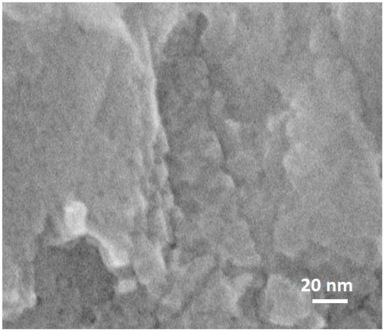
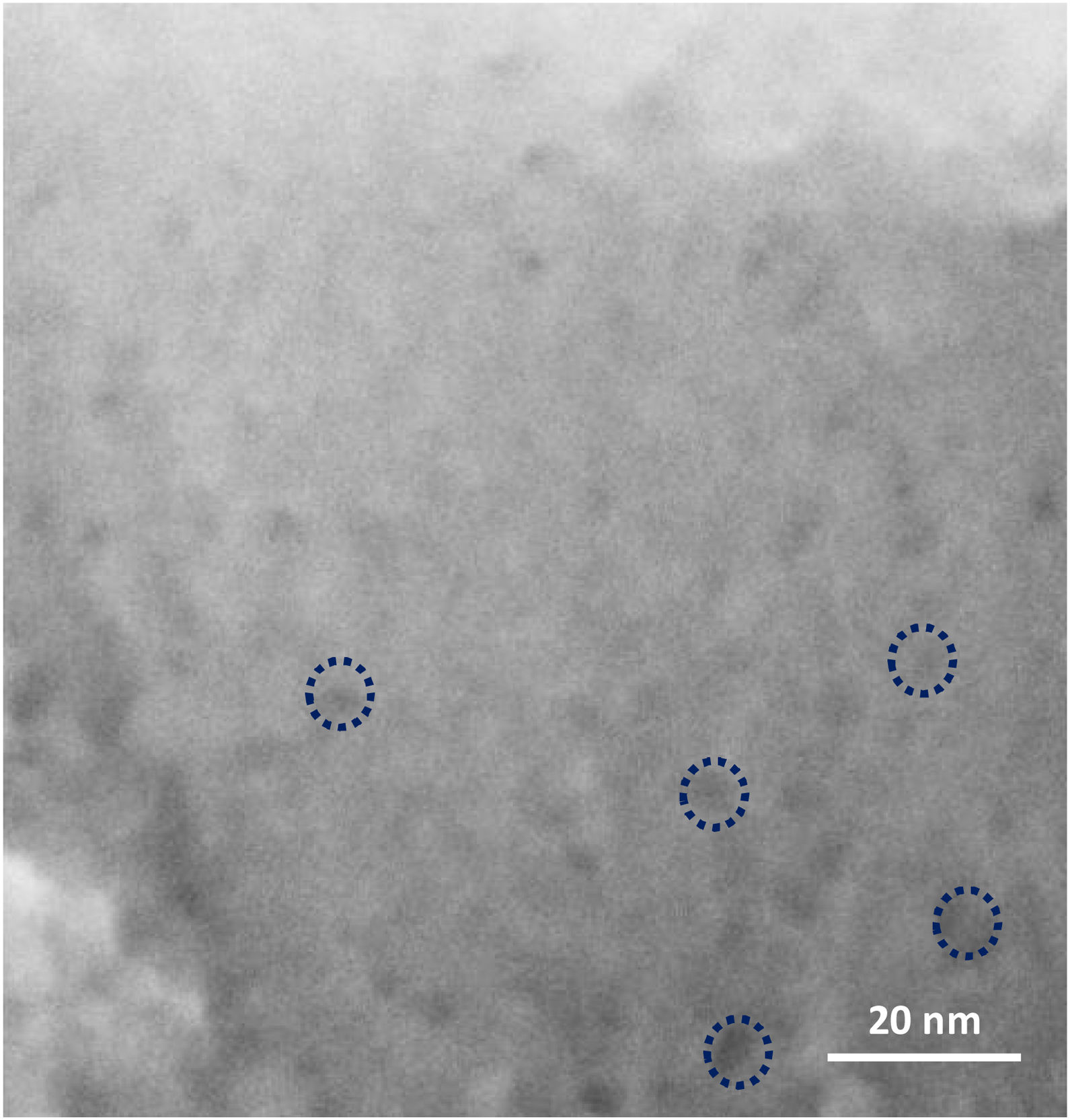
On further magnifying the crystals in the films (Fig. 9, 1 million times), small defects in the shape of holes could be seen on the grains, which shows that mesopores are present in the grains. However, it might be hard to recognise the mesopores due to the quality of the instrument, as mentioned earlier. According to the literature [41,59,60], mesopores are counted as a kind of defect in zeolite film. As a matter of fact, diffusion of the molecules through the micropores is counted as a slow process which normally results in better separation in zeolite film. Mesopores due to bigger pore diameter changes the diffusion mechanism to Knudsen diffusion with much higher diffusivity [61]. This leads to a decrease in the separation performance of the zeolite film.

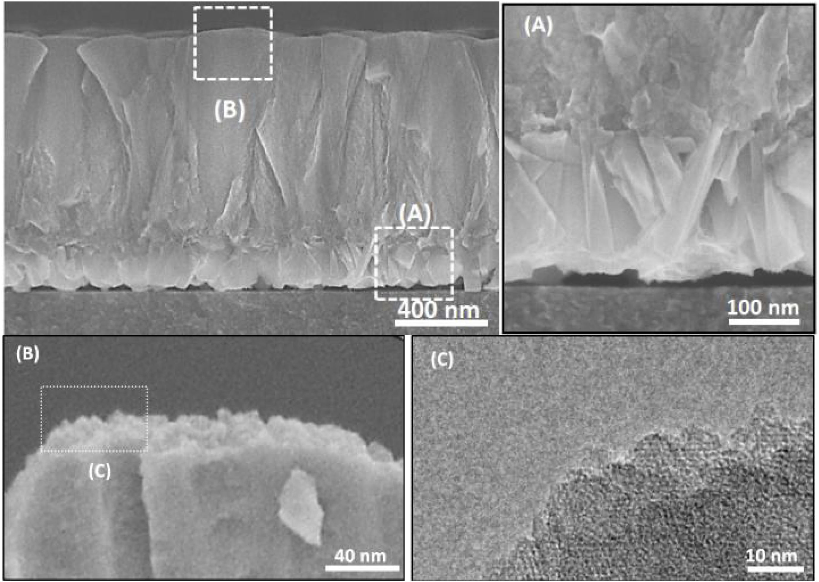
To investigate how these mesopores appear, a film was grown on amorphous carbon wafers for 120h. This led to physically hindering the film growth from the bottom (no diffusion of nanoparticles from the synthesis solution) while the top side was exposed to the synthesis solution. The aim was to compare the morphology (after growth) of a surface, exposed to synthesis solution and the side which was not exposed to the synthesis solution. Based on the hypothesis for growth mechanism (sub-colloidal particles in the synthesis solution arriving at the crystal surfaces contributed to the seed growth and subsequent film formation), randomly sub-colloidal particles arrive to the surface of crystals. This leads to an uneven distribution of sub-colloidal particles, which results in uneven surface morphology or a surface with defects (mesoporosity). After the growth of the film to a certain thickness, the film detaches from the substrate due to the tension between film and the support with a surface that has not been exposed to the synthesis solution. A smooth face was observed to the side detached from the substrate (Fig. 10A) without any asperities. In contrast, crystalline asperities formed on the top surface in contact with synthesis solution, as revealed by SEM and TEM images (Fig. 10B and C) which suggests considerable reorganisation of the nanoparticles on the crystal surface. Consequently, the mechanism of crystal growth and inhomogeneous nanoparticle attachment on the crystals results in originating mesoporous [14,39,62].
, and upside exposed to the synthesis solution (B,C).")
The thicknesses of the films synthesised for 12, 24 and 36h, were estimated using the cross-section SEM micrographs (Fig. 10) and plotted as a function of time. The linear fitting of the data gave the growth rate (slope of the line) of 0.007μm/h at 100°C. Therefore, the film growth follows the same growth mechanism as the crystals in the synthesis solution, since same mechanism provides same growth rate. However, the growth rate of single crystal was twice as high compared to film growth as expected. The crystals grow with growth direction perpendicular to the substrate surface. But, for a single crystal, the fastest growth happens to the largest diameter [40] which makes the growth rate faster for a single crystal but with the same mechanism after the first crystal's creation.
As mentioned in the experimental part, three different supports for sample preparation specific to the characterisation method used. All the films are the same with respect to the growth mechanisms, since, they all had the same growth rates. But, for investigation of film growth by SEM, silicon wafers had to be used due to the ease of processing. For the TEM sample preparation, to achieve a specimen transparent for electron beam, Cu TEM grids had to be used to grow the film. And to demonstrate the difference between the film in contact with the synthesis solution from the beginning of the film growth and the one which comes in contact with the synthesis solution at a later time, carbon wafers had to be used to achieve self-standing films, on detachment from carbon wafers due to the tensions between the film and the substrate. The self-standing film demonstrated the difference in the pattern of growing, revealed how exposing to the synthesis solution would change the morphology. Worthy to mention that the only difference between the grown film on these three supports is the direction of the growth, as mentioned earlier. For instance, for the carbon wafer, after detaching from the support, seeds would grow in different plane (even from the detached side from carbon wafer on coming in contact with synthesis solution), while the film grows only from the top in case of silicon wafer.
ConclusionSeed growth on silicon substrate took place in the early stages of hydrothermal treatment revealed by micro study of film formation from seeds. Moreover, by the graphical investigation extracted by SEM and TEM, the mechanism of film growth and possible defects formation i.e. grain boundaries, mesopores, etc. were exhibited. The sub-colloidal particles in the synthesis solution arriving at the crystal surfaces contributed to the seed growth and subsequent film formation which was defined as growth mechanism. Then, this mechanism led to mesopores’ formation in the grains of films. The growth mechanism of the first created crystals in the synthesis solution was found to be the same as film growth due to same growth rate.
Declaration of interestsThe authors declare no conflict of interest.
M. S. Nabavi acknowledges Mojtaba Sinaei for the help for providing the schematics. F. Akhtar Acknowledges, the funding for NANOCONTROL Project from FORMAS; grant no. 2016-01099, and the funding for NANOBIOGAS project from Swedish research council (VR); grant no. 2018-04407. J. Mouzon acknowledges Hanhschin Stephan for TEM sample preparations.
The following are the supplementary data to this article:

