


In this work it is demonstrated the capacity of the sol–gel process to obtain materials with different phases, using the same chemical composition, and modifying only the conditions of hydrolysis and condensation. This method combined with the polymer sponge replica technique allowed to obtain a porous and three-dimensional scaffold, called core, consisting mainly of calcium phosphates. Additionally, due to the versatility of the sol–gel process, this core was coated with additional phases, constituted by silicon and magnesium, obtaining multilayer scaffolds. The scaffolds were physically and chemically characterized and the in vitro bioactivity was evaluated by immersion in simulated body fluid. The results of in vitro bioactivity showed that the core revealed a lamellar microstructure with some apatite precipitates after 14 days, while the multilayer scaffolds presented precipitates over the whole surface in only 3 days. The accelerated bioactivity and the general properties of the multiphase and multilayer scaffolds show the potential of this material in the area of tissue engineering.
En este trabajo se demuestra la capacidad del proceso sol-gel en la obtención de materiales con diferentes fases, usando la misma composición química, y modificando únicamente las condiciones de hidrólisis y condensación. Este método combinado con la técnica de réplica de esponja polimérica permitió obtener un andamio poroso y tridimensional, llamado núcleo, constituido principalmente por fases de fosfatos de calcio. Adicionalmente, debido a la versatilidad del proceso sol-gel, este núcleo fue recubierto con fases adicionales, constituidas por silicio y magnesio, obteniendo andamios multicapa. Los andamios fueron caracterizados física y químicamente y la bioactividad in vitro evaluada mediante inmersión en suero fisiológico artificial. Los resultados de bioactividad in vitro mostraron que el núcleo reveló una microestructura lamelar con algunos precipitados de apatito después de 14 días, mientras que los andamios multicapa presentaron precipitados sobre la superficie en solo 3 días. La bioactividad acelerada y las propiedades generales del andamio multifásico y multicapa, demuestran el potencial de este material en el área de ingeniería de tejido.
Ceramics are an outstanding alternative in the repair or replacement of damaged bone. Specially, calcium phosphates stand out for their similarity to the mineral component of bone and have demonstrated excellent biocompatibility [1,2]. However, the success of an implant does not depend only on biocompatibility, other requirements are also necessary. Some of these requirements are bioactivity, osteoconductivity, osteoinductivity, biodegradability, mechanical properties, and porous structure [3,4].
It is difficult for an implant with a single calcium phosphate phase to satisfy all these characteristics. For example, tricalcium phosphate (TCP) is biocompatible and is best known for its resorbability, however, presents poor mechanical resistance [1,5,6].
In view of this problem, materials with more than one calcium phosphate phase (biphasic, triphasic and multiphasic) receive a special interest, because they can combine the advantages of individual phases [1,7].
There are many techniques to obtain multiphasic calcium phosphate materials, such as solid-state reaction, spray pyrolysis, sol–gel, hydrothermal treatments, and mechanical mixing [7]. Of all these techniques, sol–gel has the advantage of synthesizing ceramic materials at relatively low temperatures. Recently it has been used in the preparation of bioactive glass, being able to obtain crystalline phases by controlling the heat treatment [8]. The control of crystallinity is important as it will influence the mechanical properties and degradation of the material [3].
In this research, the sol–gel and polymer sponge replica techniques will be used to obtain a three-dimensional porous material (core of the scaffold). The gelation time of the sol–gel will be varied to developed different crystalline phases of calcium phosphate and other phases formed by the incorporation of silicon and lithium. The presence of silicon is due to the fact that it has been shown to influence the differentiation and proliferation of osteoblasts, that are the cells responsible for bone regeneration [9]. Instead, lithium has been added in tricalcium phosphates and has shown improved mechanical properties [10].
The core with more phases will be coated with a second chemical composition (multilayer scaffold) to improve bioactivity. This second composition will have a lower percentage of phosphorus and a higher percentage of silicon with respect to the chemical composition of the core. In addition, the calcium ions will be doped with magnesium in three different percentages to improve the cellular behaviour [11,12]. Gu et al. [11] demonstrated that TCP scaffolds doped with 1% MgO could improve the migration and spreading of cells such as human bone marrow mesenchymal stem cells and human umbilical vein endothelial cells. They also observed that magnesium induces the mineralization of the extracellular matrix and favors the increase of biomarkers such as Runx2, Col-I, ALP, OCN and BSP that regulate osteogenic differentiation. Additionally, Ke et al. [12] demonstrated that the presence of MgO and SiO2 in TCP scaffolds significantly improved formation of new bone after 16 weeks of implantation compared to TCP without dopants.
Previously, multilayer scaffolds have been developed, but by doping with strontium and iron [13,14]. These ions also have positive effects during the bone regeneration process and their incorporation at low concentrations in the scaffolds accelerated in vitro bioactivity.
As far as we know, there are materials of various calcium phosphates, but no scaffold with multilayer configuration that combines a multiphasic core with outer layer containing a higher percentage of silicon and magnesium. In this study, different characterization techniques and in vitro bioactivity tests will be used to evaluate the potential of this material as a future bone implant.
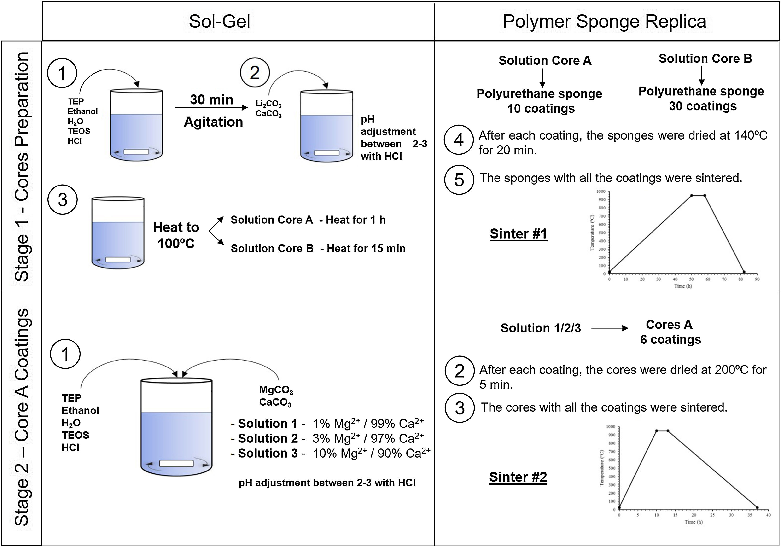
Experimental partCeramic scaffolds were prepared following the methodology in Fig. 1. The preparation process was divided into stage 1 (cores preparation) and stage 2 (core coatings).

Table 1 shows the reagents and quantities used for the scaffold core and the external coatings doped with magnesium in three different concentrations. All reagents were supplied by Sigma-Aldrich, except the magnesium carbonate from ACROS organics.
Chemical composition and reagents used in the preparation of the cores and external coatings.a
| Scaffold | Chemical composition (mol%) | Triethyl phosphate TEP (ml) | Tetraethyl orthosilicate TEOS (ml) | Li2CO3 (g) | CaCO3 (g) | MgCO3 (g) | Substitution of Ca2+ by Mg2+ |
|---|---|---|---|---|---|---|---|
| Core A/B | SiO2–25P2O5–6Li2O–68CaO | 10.2 | 0.38 | 0.5 | 8.04 | – | – |
| CoreA-1Mg | 29SiO2–3P2O5–67.3CaO–0.7MgO | 11.2 | 0.1 | 1% | |||
| CoreA-3Mg | 29SiO2–3P2O5–66CaO–2MgO | 1.63 | 11.03 | – | 11 | 0.3 | 3% |
| CoreA-10Mg | 29SiO2–3P2O5–61CaO–7MgO | 10 | 1 | 10% |
Stage 1, the cores were obtained by following these steps: (i) mixing of the reagents, (ii) agitation to produce the hydrolysis, (iii) addition of the carbonates, (iv) heating the solution to 100°C for 1h (solution A) and 15min (solution B), (v) immersion of the polyurethane sponge (20ppi, 13mm Ø×10mm long), (vi) centrifugation of the sponge at 200rpm to remove the excess solution, (vii) drying in the oven, and (viii) sintering at 950°C. Given the gelation level of the solutions, and to ensure the template's macroporosity, steps (v–vii) were repeated 10 times for solution A and 30 times for solution B.
Stage 2, the core coating was made following these steps: (i) mixing of the reagents, (ii) immersion of the cores, (iii) centrifugation, (iv) drying in the oven and (v) sintering at 950°C. Steps (ii–iv) were repeated 6 times for each type of coating.
The X-ray diffraction (XRD) technique was followed to evaluate the crystalline phases of the ceramic scaffolds. The Bruker – AXR D8 Advance diffractometer was used with secondary graphite monochromator and Cu Kα radiation (1.5418740Å) with Bragg–Brentano thetha–2thetha geometry. The X-ray tube operating conditions were 40kV and 30mA, and the test conditions were angles 2θ from 10° to 40° with 0.02 steps by counting 8s per step. The diffractograms were analyzed with the Match! Software, version 3.11.2.188, using the database provided by the Crystallography Open Database (COD).
A scanning electron microscope with energy dispersive X-ray spectroscopy (SEM-EDX) (Hitachi S-3500N and INCA system by Oxford Instrumental Analytical) was used to evaluate the microstructure and qualitatively the chemical composition of the scaffold surface.
Raman spectra were acquired by a LabRAM HR 800 Raman system brand Horiba-Jobin Yvon with an integrate Olympus BX41 confocal microscope. Spectra were collected between 300 and 1300cm−1 at a resolution of 1cm−1 using a 514nm laser.
The mercury porosimetry technique was followed to determine pore distribution and porosity <300μm. A Poromaster 60 GT Quantachrome instruments was used, with pressure between 0.851psi and 59153.25psi. The pycnometer with water, followed by the application of Archimedes’ principle, was employed to determine porosity >300μm.
A total of 15 samples of each type (8.5mm diameter and 7.0mm high) were tested in compression using a Simple Manual Test Stand (NEURTEK instruments SVL-1000N). Force was applied constantly over the entire sample surface. A digital force gauge dst/dsv SERIES was employed to record force until the scaffold completely broke.
Porosity and compressive strength tests were performed on the Core A and CoreA-10Mg scaffolds as representative samples of the other scaffolds.
Scaffolds’ in vitro bioactivity was evaluated by soaking them in simulated body fluid (SBF) from 3 days to 28 days at 37°C according to Standard ISO/FDIS 23314:2014 [15]. The sample was evaluated by SEM-EDX after each testing time. Ion exchange was evaluated by inductively coupled plasma optical emission spectrometry (ICP-OES) with Thermo iCAP 6500 DUO equipment. For this purpose, an aliquot of the resulting SBF was taken for the analysis. The remaining chloride ions in the SBF aliquot were analyzed by the ion chromatography technique (IC) using Metrohm equipment.
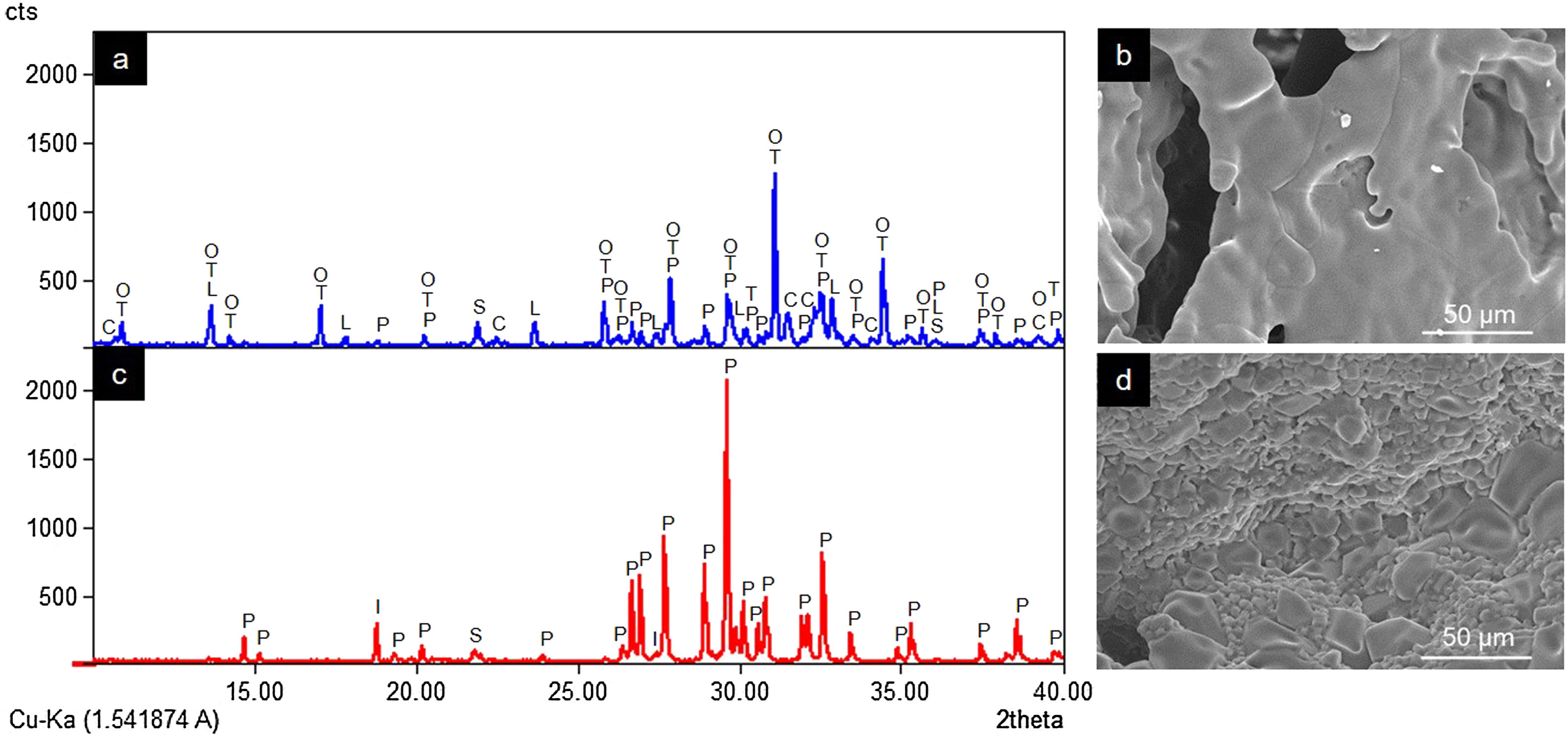
ResultsCharacterization of coresThe crystalline phases formed in Cores A and Core B are seen in Fig. 2, together with the surface images obtained by SEM.
 and Core B (c and d) (P: Ca2P2O7, I: Li(PO3), S: SiO2, T: β-Ca3(PO4)2, L: LiCa(PO4), O: Ca9.95Li1.05(PO4)7, C: Ca5(PO4)3Cl).")
Core A (Fig. 2(a) and (b)) presented mostly the β-TCP phase (COD 96-151-7239), and the phases with the phosphate group (PO4)3−, but with lithium and chlorine: Ca9.95Li1.05(PO4)7 (COD 96-152-6054); LiCa(PO4) (COD 96-722-2995); Ca5(PO4)3Cl (COD 96-101-917, COD 96-210-5266). The other phase that Core A less intensely presented was the calcium pyrophosphate phase (Ca2P2O7 – CPP) (COD 96-100-1557) and the SiO2 phase (COD 96-900-8225). This core had a smooth surface, and the edges of a possible hexagonal grain were noticed in some areas. The Ca/P ratios on the sample surface were 1.06 and 1.40. The presence of chlorine and silicon was also detected, but the latter was zero on some surface points.
Core B (Fig. 2(c) and (d)) presented mostly the Ca2P2O7 phase, followed by the Li(PO3) phase (COD 96-210-2137) and the SiO2 phase. This core was characterized by a surface made up of different sized hexagonal grains measuring ∼10–15μm on average. The Ca/P ratios on the sample surface were 0.93 and 1.09. Silicon was also detected, but only on some surface points.
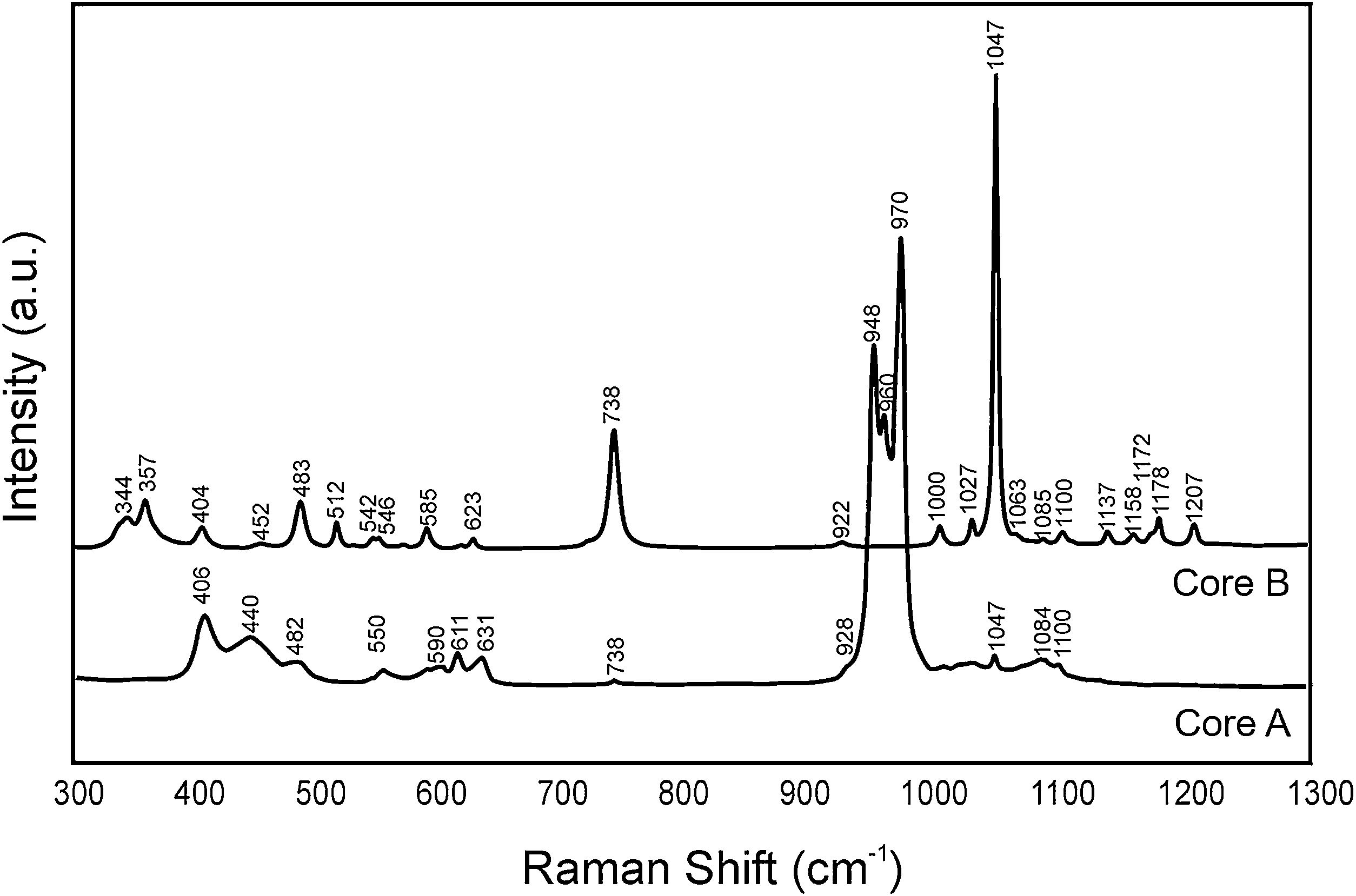
Fig. 3 shows the Raman spectra of both cores. Table 2 indicates the vibration groups assigned to each frequency. In Core A, the characteristic bands of the PO43− group of the TCP phase appeared, including calcium phosphate substituted for lithium and chloroapatite. In Core B, the vibrations of the P–O–P and PO3 groups corresponding to the CPP phase, or even the Li(PO3) phase, were identified.

Frequencies of the bands observed in the Raman spectra of Core A and Core B.
| Raman shift (cm−1) | Vibrational group | Ref. | |
|---|---|---|---|
| Core A | Core B | ||
| – | 344 | δ (PO3) sym stret | [16] |
| – | 357 | δ (PO3) sym stret | [16,17] |
| – | 404 | δ (PO3) sym stret | [16] |
| 406 | – | ν2 (PO4)3− | [17] |
| 440 | – | ν2 (PO4)3− | [17] |
| 482 | 483 | δ (PO3) sym stret | [16] |
| – | 512 | δ (PO3) sym stret | [16,17] |
| – | 542 | δ (PO3) asym stret | [16] |
| 550 | – | ν4 (PO4)3− | [17] |
| – | 585 | δ (PO3) asym stret | [16] |
| 590 | – | ν4 (PO4)3− | [17] |
| 611 | – | ν4 (PO4)3− | [17] |
| – | 623 | δ (PO3) asym stret | [16] |
| 631 | – | ν4 (PO4)3− | [17] |
| 738 | 738 | ν(P-O-P) sym stret | [16,17] |
| 928 | 922 | ν(P-O-P) asy stret | [16] |
| 948 | – | ν1 (PO4)3− | [17] |
| 960 | – | ν1 (PO4)3− | [17] |
| 970 | – | ν1 (PO4)3− | [17] |
| – | 1000 | ν(PO3) sym stret | [16] |
| – | 1027 | ν(PO3) sym stret | [16] |
| 1047 | 1047 | ν(PO3) sym stret | [16,17] |
| – | 1063 | ν(PO3) sym stret | [18] |
| 1084 | 1085 | ν(PO3) asym stret | [18] |
| 1100 | 1100 | ν(PO3) asym stret | [16] |
| – | 1137 | ν(PO3) asym stret | [16,17] |
| – | 1158 | ν(PO3) asym stret | [18] |
| – | 1172 | ν(PO3) asym stret | [16] |
| – | 1178 | ν(PO3) asym stret | [17] |
| – | 1207 | ν(PO3) asym stret | [16] |
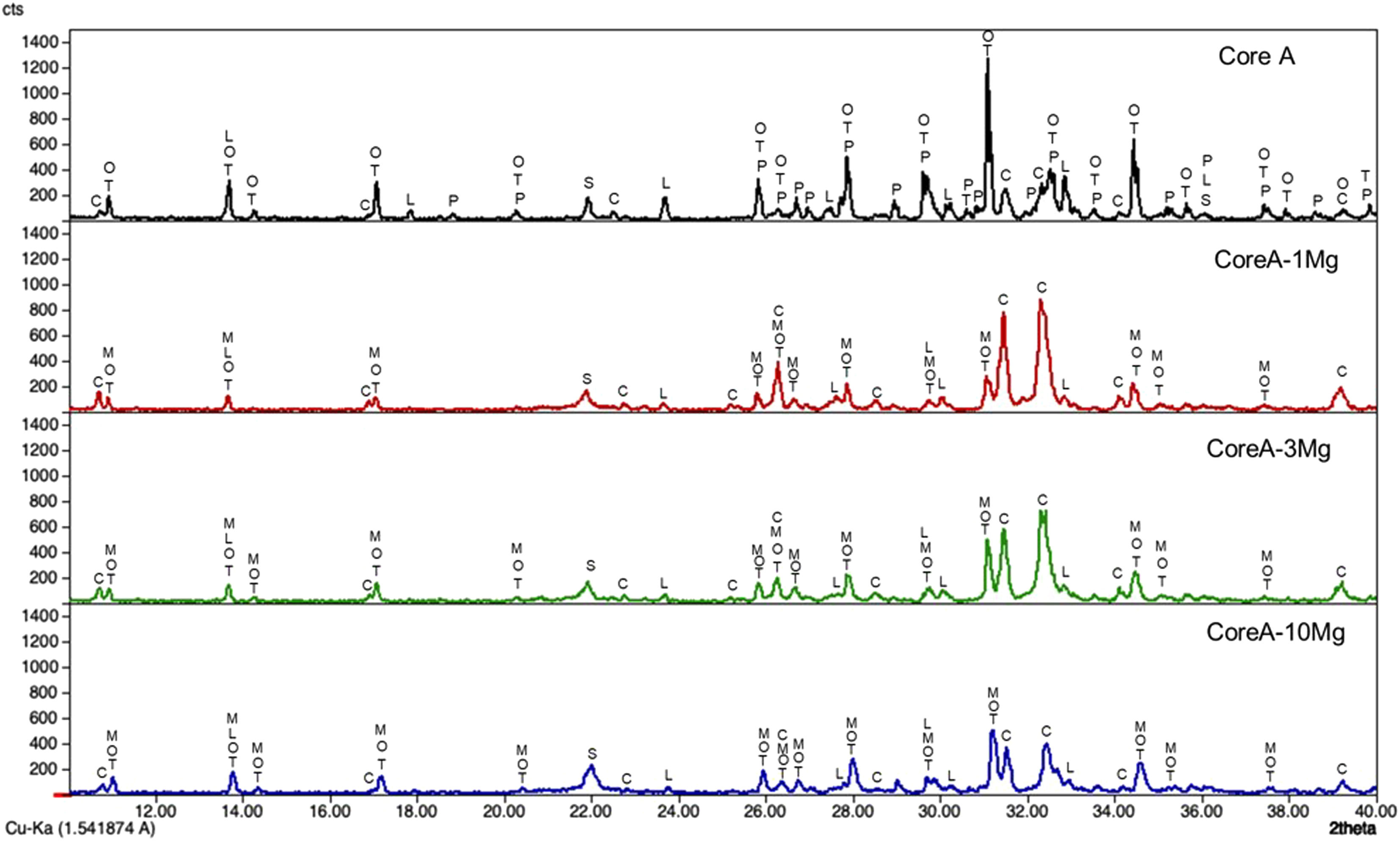
Fig. 4 presents the diffractograms of the CoreA-XMg scaffolds. These samples showed the following phases: β-TCP (COD 96-151-7239); Ca10.115Mg0.385(PO4)7 (COD 96-901-2137); LiCa(PO4) (COD 96-722-2995); Ca9.95Li1.05(PO4)7 (COD 96-152-6054); Ca5(PO4)3Cl (COD 96-101-917, COD 96-210-5266); SiO2 (COD 96-900-8228).
2, M: Ca10.115Mg0.385(PO4)7, L: LiCa(PO4), O: Ca9.95Li1.05(PO4)7 and C: Ca5(PO4)3Cl.")
When Core A was coated, the CPP phase peaks completely disappeared, while the phase of the calcium phosphate substituted for magnesium appeared. Moreover, when magnesium doping increased, the phase of calcium phosphate substituted for magnesium also increased, while the phase chloroapatite decreased. During intermediate doping (CoreA-3Mg), the intensity of these peaks was equal and inversed during the minimum (CoreA-1Mg) and maximum (CoreA-10Mg) doping.
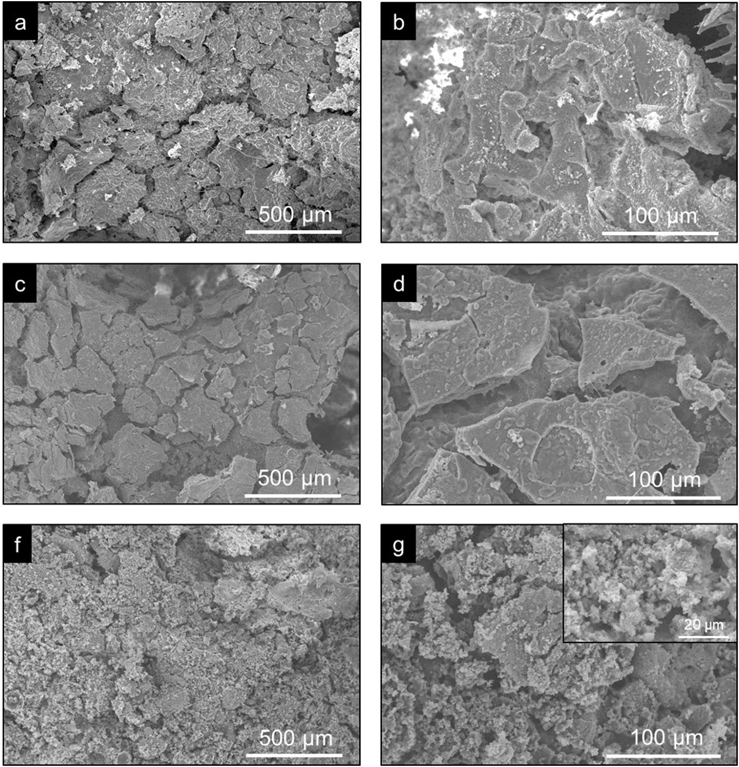
Fig. 5 shows the SEM images of the CoreA-XMg scaffolds. Two images are presented per scaffold: one with low magnification, where the microstructure of the new coatings made on Core A are seen; the second images are presented at high magnification, where these coatings can be seen in more detail. On the CoreA-1Mg and CoreA-3Mg scaffolds, the coating-formed plates are distributed over the entire Core A surface. The CoreA-10Mg scaffold coating presented no defined plates like the previous scaffolds. In this case, different sized particles covered the entire surface.
 the CoreA-1Mg, (c and d) CoreA-3Mg and (f and g) CoreA-10Mg scaffolds.")
The EDX performed on the surface of these coatings revealed the presence of calcium, phosphorus, chlorine, magnesium and silicon. The atomic percentage averages of magnesium and silicon at the different points were 0.45% and 15.15% for the CoreA-1Mg scaffold, 1.42% and 21.27% for the CoreA-3Mg scaffold and 4.75% and 16.09% for the CoreA-10Mg scaffold, respectively.
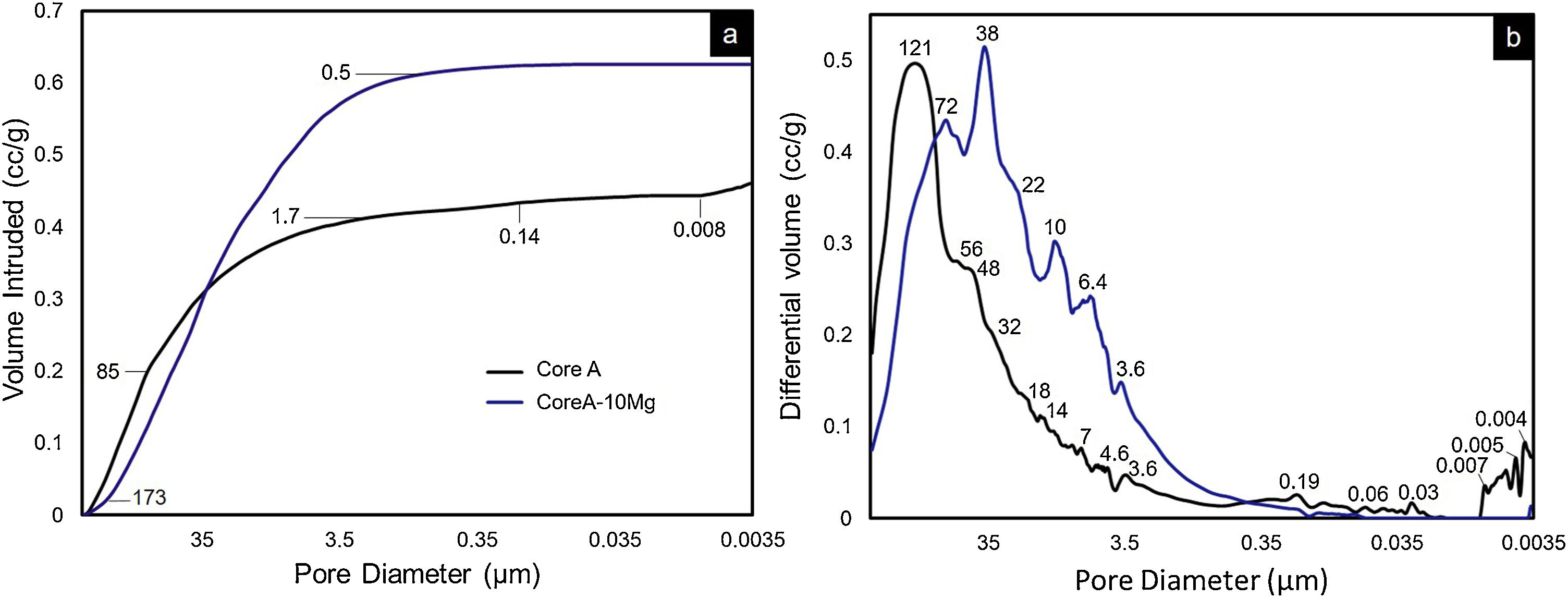
On scaffolds’ porosity, the mercury porosimetry technique and pycnometer allowed information on both micro- and macroporosity to be acquired. Fig. 6 shows the mercury porosimetry curves and Table 3 presents the total microporosity, which is divided into intra- and interparticle porosity. Core A presented more interparticle pores compared to intraparticle ones. The CoreA-10Mg scaffold displayed the same mercury intrusion behavior, but despite the percentage of intraparticle pores being approximately the same, the percentage of interparticle pores was higher compared to Core A. As a result, the total microporosity of Core A was 57.46% and that of CoreA-10Mg was 65.49%. The pore distribution curve shows that Core A had the most pores, approximately between 250μm and 1.7μm, with a mean value of 121μm. The pore distribution of CoreA-10Mg was roughly between 173μm and 0.5μm, with a mean value of 38μm.
 cumulative and (b) differential volume intruded vs. pore diameter of the Core A and CoreA-10Mg scaffolds.")
Summary of the porosity and compressive strength of the Core A and CoreA-10Mg scaffolds.
Table 3 also shows scaffolds’ macroporosity obtained by pycnometry and Archimedes’ principle. For Core A it was 72.50% and 53.29% for the CoreA-10Mg scaffold. Finally, the compressive strength presented in Table 3 falls within a range of 0.38–1.84MPa for the Core A and one of 0.40–2.00MPa for the CoreA-10Mg scaffolds.
Evaluation of the in vitro bioactivity of the Core A and CoreA-XMg scaffoldsFig. 7 shows the SEM images obtained after the in vitro bioactivity evaluation of Core A. Fig. 7(a) depicts how the surface presented no morphological changes up to 7 days immersed in SBF, when the original smooth scaffold surface (Fig. 2(b)) began to dissolve, shown by the arrow in Fig. 7(b). After 14 days in SBF (Fig. 7(c)), the zone observed at 7 days resembled a lamellar structure surrounded by the original microstructure. Additionally, spheres with an apatite-like appearance precipitated on the entire surface. On the following days (21 and 28) the lamellar structure continued to evolve until it occupied most of the surface which was, in turn, covered by a bigger number of precipitates (Fig. 7(d) and (e)). On average, the Ca/P ratios of lamellas were (1.34±0.24) in the middle and (1.53±0.16) on the edge of lamellas. For precipitates, the Ca/P ratio was (1.31±0.12), and other elements like silicon and chlorine were also detected.
 3 days, (b) 7 days, (c) 14 days, (d) 21 days and (e) 28 days.")
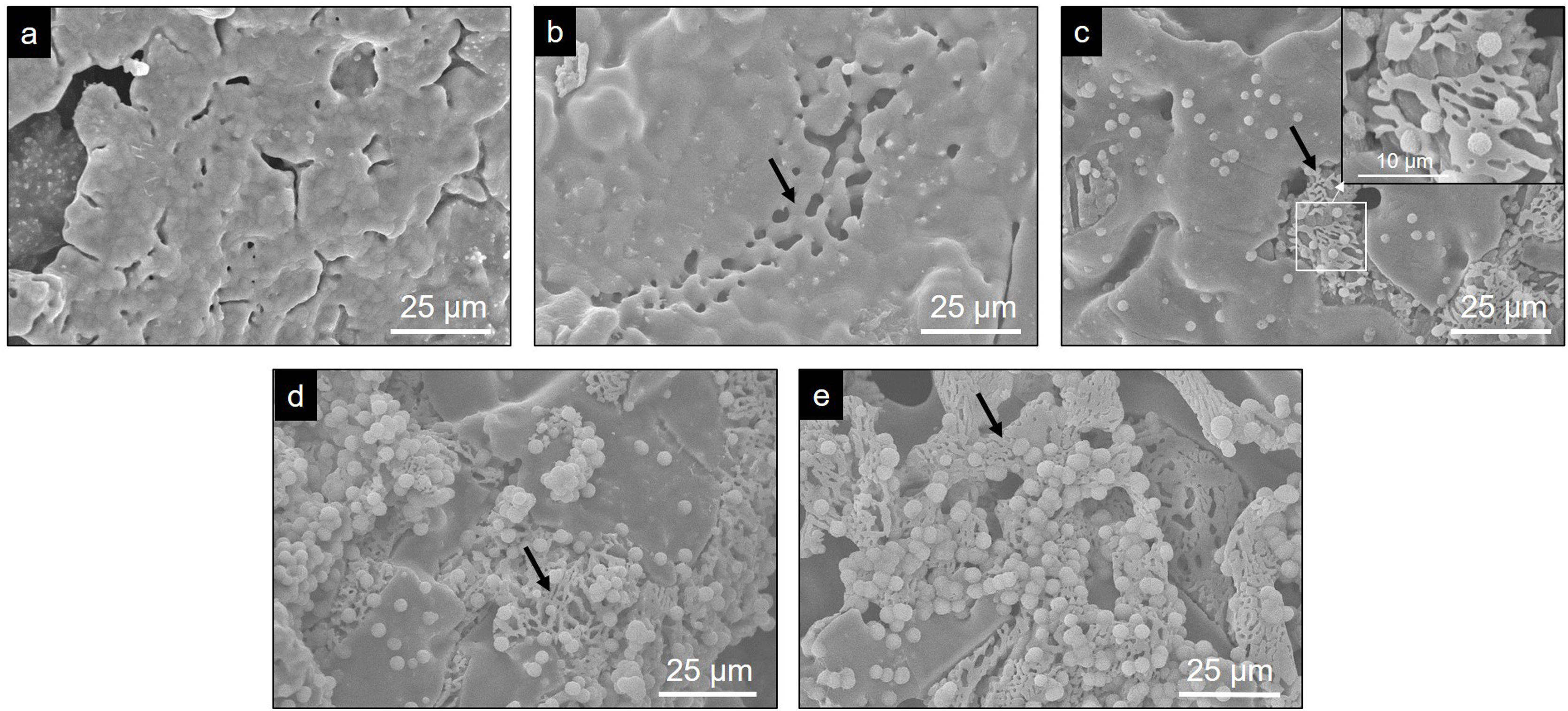
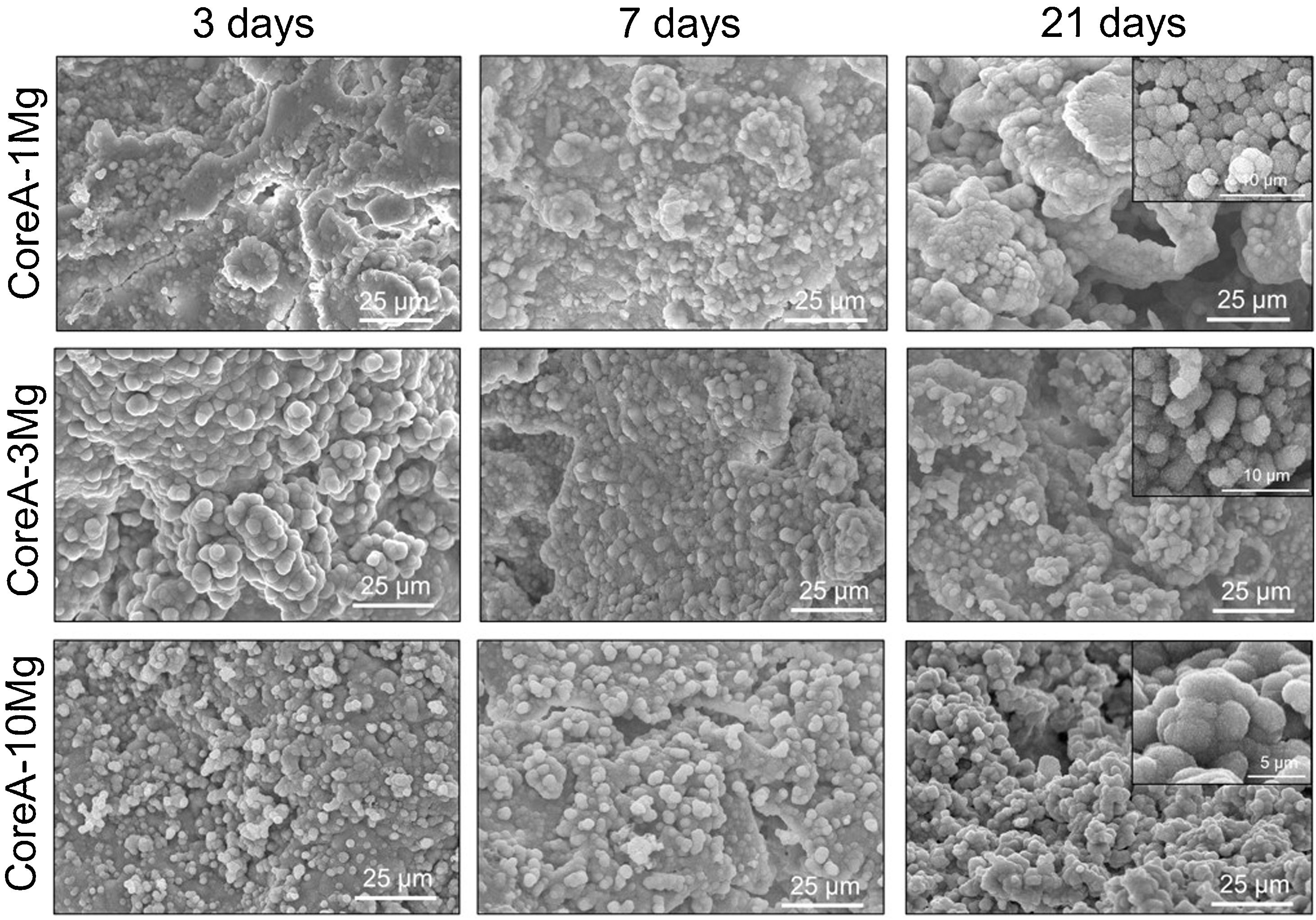
Fig. 8 shows the SEM images obtained after the in vitro bioactivity evaluation of CoreA-1Mg, CoreA-3Mg and CoreA-10Mg. The three afore-mentioned scaffolds presented precipitates after 3 days in SBF and even remained until 28 days (image not shown). These precipitates distributed over the sample’ entire surfaces were globular in shape with needle-like structures.

The Ca/P ratio of precipitates changed over time and, due to magnesium doping, the (Ca+Mg)/P ratio was also considered. From 3 to 21 days, the CoreA-1Mg scaffold presented an average Ca/P ratio of (1.21±0.13) and a (Ca+Mg)/P ratio of (1.31±0.16). However, at 28 days, the Ca/P ratio changed to (1.52±0.03) and the (Ca+Mg)/P ratio to (1.57±0.04).
The CoreA-3Mg scaffold presented a Ca/P ratio of (1.46±0.18) and a (Ca+Mg)/P ratio of (1.54±0.22). Finally, the CoreA-10Mg scaffold had a Ca/P ratio of (1.64±0.22) and a (Ca+Mg)/P ratio of (1.77±0.22).
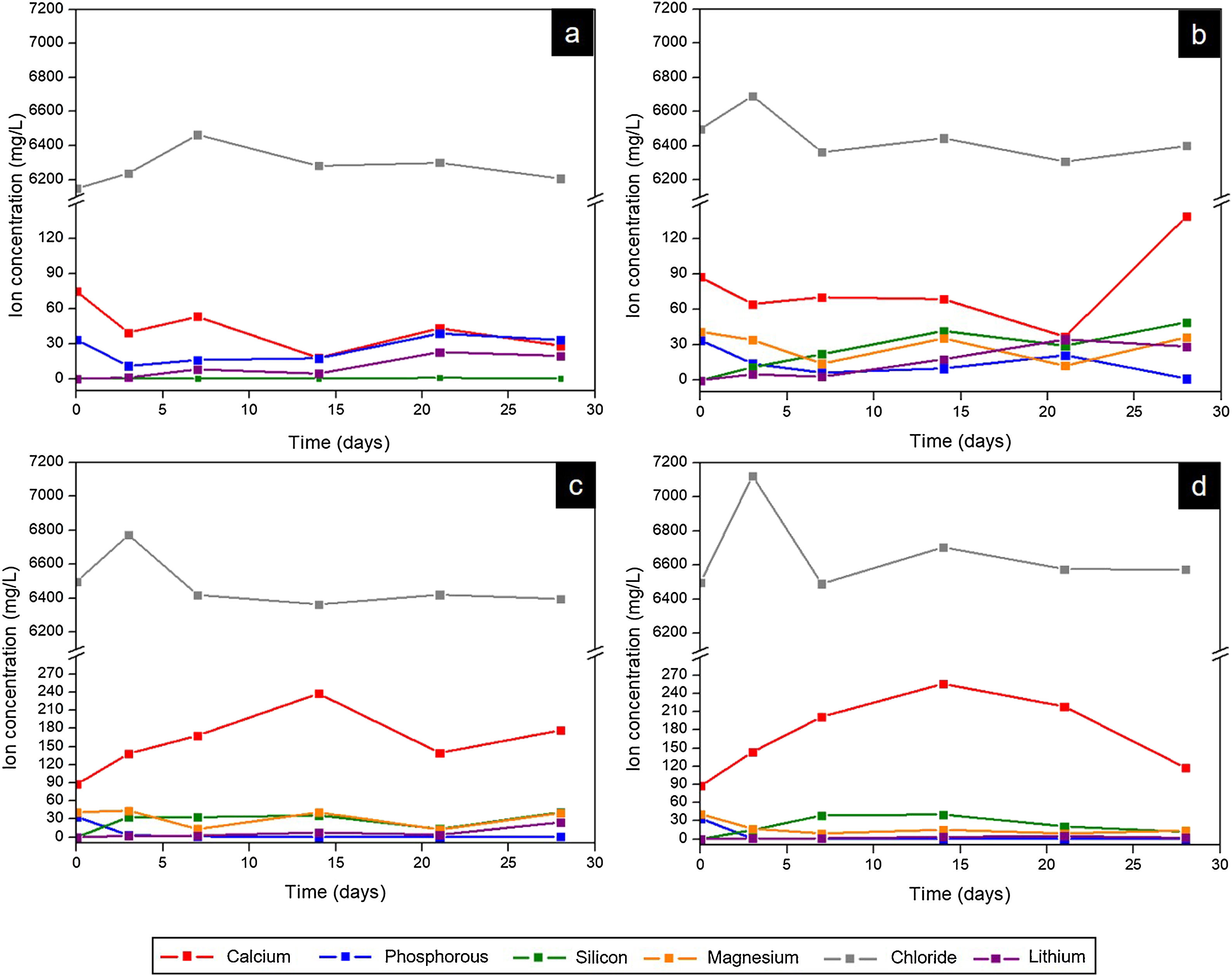
Fig. 9 presents the curves obtained by ICP-OES and IC for the different scaffolds. It shows the concentration of ions in SBF during the evaluation of the in vitro bioactivity. The ionic behavior in the SBF that was in contact with Core A (Fig. 9(a)) showed: (i) calcium concentration generally lowered from the first day to 28 days, and displayed oscillatory behavior at intermediate times; (ii) phosphorous concentration lowered on day 3, but this concentration rose at other times; (iii) silicon whose initial concentration in SBF was zero, remained the same for the rest of the study time; (iv) lithium whose initial concentration was also zero, progressively increased during the rest of the study time; and (v) chloride concentration rose on day 7, and lowered to the initial concentration values for longer immersion times.
 Core A, (b) CoreA-1Mg, (c) CoreA-3Mg, and (d) CoreA-10Mg.")
Fig. 9(b)–(d) shows the curves of the CoreA-1Mg, CoreA-3Mg and CoreA-10Mg scaffolds. In summary, the ionic behavior was as follows: (i) chloride ions showed similar behavior to the core but rose on day 3; (ii) calcium ions concentration in the CoreA-1Mg scaffold lowered until 21 days when it rose, while the other scaffolds showed opposite behavior; (iii) silicon concentration rose in the early day, except for the CoreA-10Mg scaffold which showed a slight adsorption after 28 days; (iv) phosphorous concentration generally lowered in the SBF, (v) lithium concentration rose over time and finally (vi) part of the magnesium ions from the SBF was adsorbed by the scaffolds after 28 days, mainly on the CoreA-10Mg scaffold.
DiscussionCharacterization of coresCores A and B were manufactured by the same method. The only difference between the two cores was the heating time of the sol solution (Fig. 1). This variation led to both cores presenting a different chemical phase, according to the XRD and Raman characterization results.
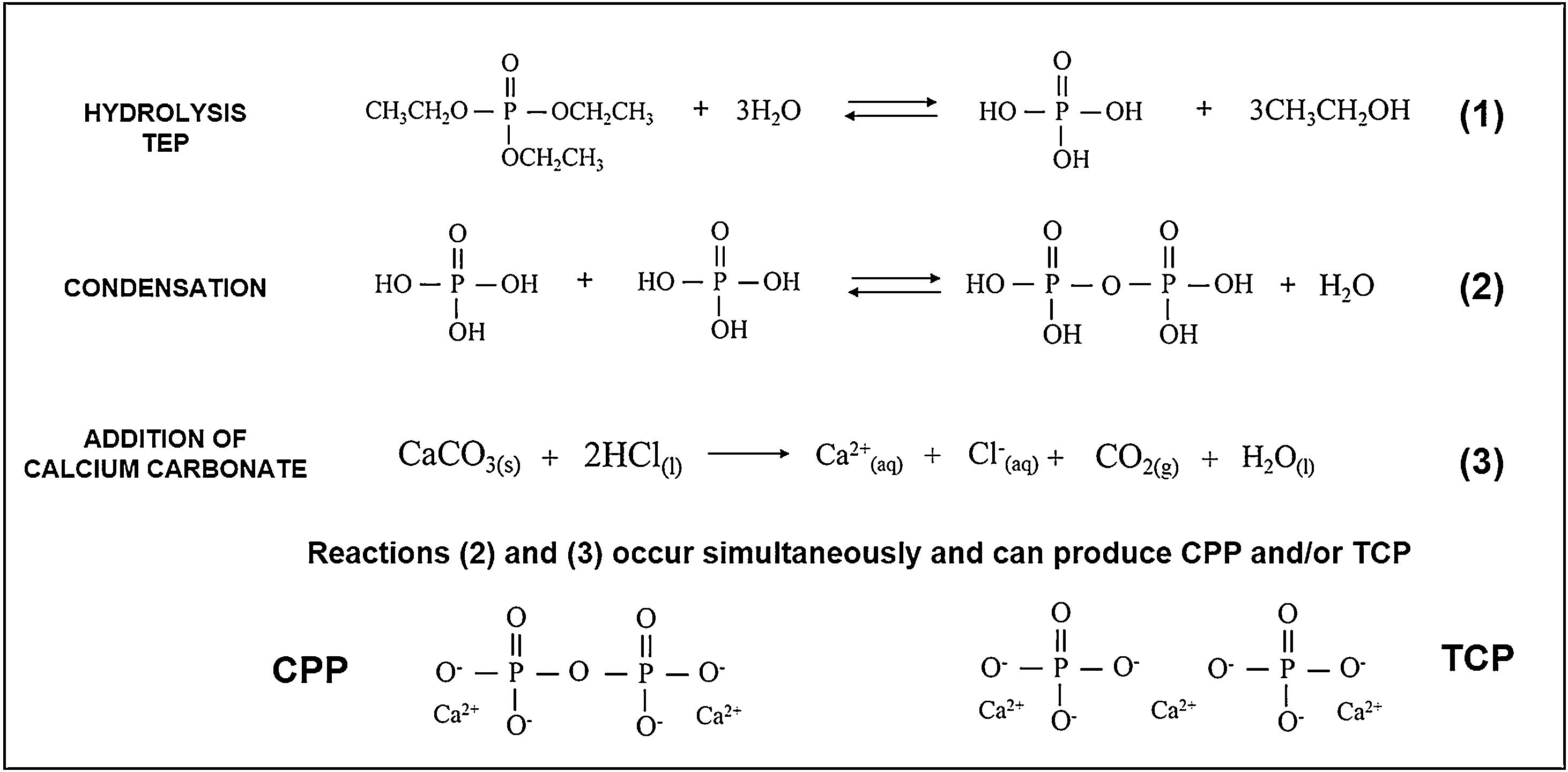
While preparing cores, the hydrolysis of TEOS and TEP first occurred, and then condensation was activated by adding carbonates. An acid catalyst was used to accelerate the hydrolysis reaction and, at the same time, to avoid rapid gelation in the condensation reaction. Fig. 10 summarizes the hydrolysis and condensation reactions of TEP. It is worth mentioning that although complete TEP hydrolysis can be seen, it rarely occurs. Therefore during condensation, water or alcohol can be obtained as a product of the reaction depending on the degree of TEP molecule hydrolysis. The reaction that took place while adding calcium carbonate is also shown. Note that it was the majority carbonate in the reaction, and that lithium carbonate was also added. As all these processes occurred simultaneously, calcium ions were incorporated into the reaction, interfered with condensation, and could form TCP and/or CPP molecules.

The extension of the reactions (see Fig. 10) was modified according to heating time to generate the solution of Cores A and B. The difference in the two solutions was the amount of water in the final solution, which modified the condensation process. In solution A, and after heating for 1h, all the water had evaporated and, therefore, all the added calcium ions came into contact with the hydrolyzed and condensed molecules, which favored the formation of TCP (Ca/P=1.5). Solution B, with a 15-min heating time, still held most of the initial water. Visually, the solution separated into two phases: one oily and one liquid. The oily phase contained the molecules produced by hydrolysis and condensation, and the liquid phase was water. Thus, water molecules tended to dissolve calcium ions and leave the oily phase with a calcium deficit, which favored CPP formation (Ca/P=1).
In the presence or absence of water molecules, this mechanism of action of calcium, explains the existence of two cores with different phases. The formation of the TCP or CPP phases, due to the deficiency (or not) of calcium ions, has also been observed by other authors [19]. In Core A, the other phases containing the PO43− group formed along with the TCP phase, but were combined with other ions like lithium and chlorine. These ions were in the solution and, like calcium, they can form part of condensation. Consequently, other phases were obtained. In sol–gel synthesis is usual to find the formation of additional or residual phases to those desired [20].
Both cores were constituted of calcium phosphates, which are interesting as biomaterials. The main components were TCP and CPP, which are biocompatible [1,21]. Another phase present as chloroapatite, is not a good biomaterial at high concentration because it acidifies the environment, however, thanks to this, it can help in the dissolution of alkaline salts, digest the organic matrix and activate the bone resorption process produced by osteoclasts [22,23]. The phases of calcium phosphate substituted for lithium are phases that, as far as we know, have barely been studied. However, it is known that lithium is found in small traces in the human body and it stimulates the proliferation of certain cells and bone densification, as well as improving the mechanical properties by adding it to TCP [10,23].
The presence of a high number of phosphate phases in the Core A, makes it an ideal material to study the synergistic effects between the phases. Additionally, in order to improve the behavior of the core, it is coated with phases constituted of silicon and magnesium, obtaining a multilayer scaffold. The study of Core B under the same conditions is proposed for a future work.
Characterization of the CoreA-XMg scaffoldsThe increase in intensity of the silica peaks in the three diffractograms in Fig. 4 corroborates the presence of the external coatings, which presents more silicon than the core. The decrease in the CPP phase was attributed to the diffusion processes that occur during the second sintering where the pyrophosphate was redistributed to form a phase with a Ca/P ratio above 1. The presence of magnesium also explained the disappearance of CPP. Different studies have shown that it tends to preferentially stabilize the TCP phase [24]. The intensity of the XRD peaks decreased with increased magnesium, which could imply loss of crystallinity.
Competition occurs between the formation of calcium phosphate with magnesium and chloroapatite. Compared to Core A, the intensity of the phase chloroapatite increased with coatings. However, this phase decreased with increased of magnesium because the formation of calcium phosphate substituted for magnesium phase was favored.
The coated scaffoldś surface changed (Fig. 5) compared to the Core A surface (Fig. 2(b)). The coating of the CoreA-1Mg and CoreA-3Mg scaffolds formed separate plates that covered the core surface. The fact that was no continuous layer could be attributed to the contractions that occurred during heat treatment. The reason why the CoreA-10Mg scaffold coating did not form plates, but different sized precipitates instead, could be due to the amount of magnesium that now competed with calcium. According to the studies by Zhou and co-workers, Ca2+ and Mg2+ ions can react with PO43− to form needle and plate particles, but when both ions coexist in the PO43− reaction, they form a mesoporous structure [24].
The atomic percentage of silicon was practically the same in all three scaffolds. Thus the difference in peak intensity, observed by XRD, could be due to the difference between the crystalline and amorphous phases, which was not detected. The percentage of magnesium consistently rose with the increase in doping.
During the bone growth, the porosity is fundamental for defining the cells/scaffold interaction. In this work, pores larger than 300μm were designated as macropores, while those smaller than 300μm as micropores. Although an ideal pore size has not yet been established, it is known that both types are fundamental. Microporosity favors cells/material interaction as they are responsible for protein adsorption and retention, which will later interact with cells promote their adhesion [25]. Macroporosity is responsible for enabling cells to penetrate and migrate throughout the scaffold [25].
Microporosity increased with the coatings on the core because CoreA-10Mg scaffold surface was more porous (Fig. 5(f) and (g)) than Core A (Fig. 2). In the case of macroporosity, this decreased due to the coatings on Core A, which closed the original template pores. Despite the decreased macroporosity, another property was favored: compressive strength. As a result of increased compressive strength, the CoreA-10Mg scaffold could be compared to cancellous bone which, according to Polo-Corrales et al. [26], lies between 2MPa and 4MPa.
Evaluation of the in vitro bioactivity of the Core A and CoreA-XMg scaffoldsThe in vitro evaluation of Core A showed that the material generally behaved by dissolving its original microstructure to form a lamellar structure which was, in turn, colonized by precipitates. After 7 days the lamellas appeared together with a release of chlorides, calcium and lithium. According to the released ions, the dissolved phases could the chloroapatite and lithium phases. The average Ca/P ratio was (1.53±0.16) on the edge of lamellae, which indicates the presence of the β-TCP phase, it would suggest that the dissolved phases were the CPP, lithium phases or chloroapatite. The dissolution of the CPP phase cannot be ionically verified as other phases also contained calcium and phosphorus. However, lithium release was evident. After 14 days, precipitates appeared and adsorption of chloride and calcium occurred that could be incorporated into the new precipitates.
Globular apatite-like precipitates had an average Ca/P ratio of (1.31±0.12). Although this would not correspond to the Ca/P ratio of hydroxyapatite, the presence of both silicon and chlorine retained in the precipitate could affect hydroxyapatite detection or formation. The mechanism by which these precipitates appeared on the material's surface, together with lamellae formation, can be attributed to the presence of the β-TCP phase, according mechanism proposed by Kim et al. [27].
The in vitro behavior displayed by the CoreA-XMg scaffolds was different compared to Core A, but similar to each other. After only 3 days of being in contact with SBF, the three scaffolds showed precipitates, which covered the entire surface, and even remained until 28 days.
From the analysis done of scaffolds’ ionic behavior, it was concluded that chloride ions influenced the appearance of precipitates as this was released after 3 days (Fig. 10), which coincided with their appearance (Fig. 9). The phosphorous concentration always lowered in the three scaffolds; that is, phosphorous was adsorbed by the sample until all the phosphorus present in SBF was consumed. This adsorption is associated with the formation of precipitates.
The ionic behavior of calcium and magnesium was different in the three scaffolds. In the CoreA-1Mg scaffold, in the first days the sample adsorbed calcium and then released it after 28 days. The other two scaffolds released calcium until 14 days and then adsorbed it. This behavior is due to the doping with magnesium. The scaffolds with the highest percentage of doping initially formed the precipitates with magnesium, even adsorbing the magnesium ions from the SBF. On the contrary, the scaffold with lower percentage of magnesium formed the precipitates with calcium adsorbed from SBF. In general, lithium was released by all the scaffolds, indicating the dissolution of the coating and contact with the core. Likewise, silicon was released by scaffolds and it is suggested that the bioactivity of these is due to the greater amount of silica in the external coatings, following the mechanism proposed by Hench [28].
The Ca/P and (Ca+Mg)/P ratios in the initial times do not correspond to the hydroxyapatite ratio (1.67). However, with the immersion time this ratio increased, reaching the ratio of calcium deficient hydroxyapatite. Only the CoreA-10Mg scaffold presented hydroxyapatite ratios.
In short, the sol–gel method's versatility was demonstrated by obtaining a multiphase material of calcium phosphates. This method allowed different elements to be incorporated to form complex and varied phases. The different phases conferred Core A a bioactive characteristic, but also the development of a lamellar structure when it came into contact with SBF. By incorporating the second coatings on Core A, a multilayer scaffold with a marked bioactivity character was created. The bioactivity of the multiphase core was improved with coatings that accelerated bioactive behavior after being in contact with SBF for only 3 days. Previously, Ciro et al. [29] improved the bioactivity of material with crystalline phases of α/β-TCP, CPP and CaHPO4, by adding 10 and 15% of bioglass with composition 31SiO2–56CaO–2MgO–11P2O5. However, with the development of multilayer scaffold, besides promoting the bioactivity with the external layer, it is proposed to maintain the characteristics such as porosity and mechanical resistance provided by the composition of the core.
Previously, multilayer scaffolds doped with strontium and iron were studied, which also showed an acceleration of in vitro bioactivity [13,14]. In the case of strontium, the ion substituted the calcium silicate phase, while iron and magnesium substituted the calcium phosphate phase. Although all three studies show positive effects on bioactivity, the core of the strontium and iron doped scaffolds are different from the one used in this study and therefore cannot be directly compared.
The presence of magnesium on apatite precipitates might promote tissue growth than to its good interaction with cells, and silicon release may contribute to this process, as discussed above. Although the three doped scaffolds presented precipitates at only 3 days, the CoreA-10Mg scaffold could prove the most favorable for cells given the larger amount of magnesium contained on the surface. It is worth highlighting that, although doped coatings provide bioactivity, the core presented a chemical composition that was capable of mimicking cancellous bone with macroporosity and compressive strength.
ConclusionsIn this work, it was demonstrated the versatility of the sol–gel process in obtaining multiphase materials. Using a single chemical composition and varying the heating time of the solution, three-dimensional porous scaffolds with different crystalline phases were obtained. Additionally, through this method it was possible to obtain multilayer structures doped with silicon and magnesium in the outer layers. The multilayer scaffold developed in this work combines several chemical compositions that provide different characteristics such as mechanical strength, porosity, and in vitro bioactivity, which are difficult to obtain in scaffolds of a single chemical composition. Silicon accelerated bioactivity and the presence of magnesium in apatite precipitates can enhance cellular processes.
Conflicts of interestNone declared.
The Ph.D. student Nayarit A. Mata has been funded by a grant from the Government of Generalitat Valenciana with reference GRISOLIAP/2018/037.
