


In this study, the impact of varying spraying current on tribological performance and microstructural properties for coating was investigated. Atmospheric plasma spraying (APS) was used as the technique of depositing coatings on Q235 grade steel (equivalent to ASTM A36 mild steel). The coated samples were characterized using optical microscopy (OM), scanning electron microscopy (SEM), energy dispersive spectroscopy (EDS), adhesion testers and microhardness tester. Scratch tests were carried out under ambient and dry environments using a pin-on-plate configuration against Tungsten Carbide (WC) body (pin/stylus) for a constant load. It was found that samples sprayed under higher current had better adhesive bond and erosion wear resistance, they also had the lowest wear loss and least percentage porosity. Additionally, hardness was improved almost 10 times of the base material in comparison to lower current samples.
En este estudio se investigó el impacto de la corriente de pulverización variable sobre el rendimiento tribológico y las propiedades microestructurales para el recubrimiento del Cr2O3. La pulverización con plasma atmosférico (PPA) se usó como la técnica para depositar recubrimientos de Cr2O3 sobre acero de grado Q235 (equivalente al acero dulce ASTM A36). Las muestras recubiertas se caracterizaron usando microscopía óptica (MO), microscopía electrónica de barrido (MEB), espectroscopia de energía dispersiva (EED), probadores de adherencia y probadores de microdureza. Las pruebas se llevaron a cabo en medios ambientales y secos utilizando una configuración de pin en placa contra el cuerpo de carburo de tungsteno (WC) (pin/stylus) para una carga constante. Se encontró que las muestras rociadas con una corriente más alta tenían un mejor enlace adhesivo y una mejor resistencia al desgaste por erosión, también tenían menor pérdida de desgaste y menor porcentaje de porosidad. Además, se mejoró la dureza casi 10 veces del material base en comparación con muestras de corriente más baja.
Correctly acknowledging the primary funders and grant IDs of your research is important to ensure compliance with funder policies. We could not find any acknowledgement of funding sources in your text. Is this correct?“Your article is registered as a regular item and is being processed for inclusion in a regular issue of the journal. If this is NOT correct and your article belongs to a Special Issue/Collection please contact a.saavedra@elsevier.com immediately prior to returning your corrections.”Correctly acknowledging the primary funders and grant IDs of your research is important to ensure compliance with funder policies. We could not find any acknowledgement of funding sources in your text. Is this correct?“Your article is registered as a regular item and is being processed for inclusion in a regular issue of the journal. If this is NOT correct and your article belongs to a Special Issue/Collection please contact a.saavedra@elsevier.com immediately prior to returning your corrections.”Ceramics and ceramic coatings have a good reception for various industrial application because of their impeccable qualities of inertness under high temperatures, high strength, high hardness, wear resistance and resistance to both oxidation and corrosion at elevated temperatures. Ceramics have been used as composites in metallic matrix formation or comfortably applied as surface coatings because their production routes in bulk is a challenge, especially due to the intrinsic defects encountered during manufacturing [1–3]. Among the commonly used ceramics is sprayed coatings, which is an excellent candidate for functional and structural coating applications for wear [4], friction and corrosion protection [5]. Industrial applications of sprayed coatings is vast and wide in mining, textile, chemical, automotive, aerospace, marine structures and shipbuilding fields [6–8].Atmospheric Plasma Spraying (APS)has been used in spraying most refractory materials which are characterized with high hardness and high melting points[9]. which is a hard ceramic material with melting temperatures of about 2350°C, can be easily sprayed by APS whose plasma jet temperatures go above 2600°C, which is generally above most melting points of many ceramic materials[10,11]. APS coatings typically have inherent defects such as pores, microcracks, unmolten and semi-molten particles [11,12]. It is therefore imperative to minimize these defect levels to realize a functional coating. The microstructure and properties of any sprayed coating depends on the type of feedstock, whether wire or powder [13], the nature in which it is provided whether conventional micronized, nanosized or in a solution/suspension form [14] and the process spraying parameters used to deposit the feedstock [13,15–17]. For all engineering application, the plasma sprayed coating must possess good adhesion between the coating/substrate interface and cohesion between the build-up layers [11,14,18].
Depending on the functionality of such high quality coating, the intrinsic defects must be curtailed. Common defects in plasma sprayed coating are cracks from residual stress relaxation [18–20] and interlamellar pores between layered splats/substrate or globular pores from unmolten or partially molten particles [21]. The integrity of any plasma sprayed coating is to have as little or no defect at all. A compromise is usually reached at by having the correct particle size distribution and optimizing the particle injection conditions[22].
Many of the research works have been done to optimize the spraying parameters to achieve good functional coatings. This has been done both experimentally and empirically using mathematical modeling [16,23,24]. With these, surface engineering industry has developed and made substantial strides towards achieving ideal coatings.
The purpose of this investigation is to study the microstructure of plasma sprayed coatings and the effects that varying spraying current has on the hardness and tribological behaviour of the coatings under constant load and ambient environment. APS coating was deposited on Q235 steel substrates without pre depositing bonding coat. Friction/erosion tests were done using a Universal mechanical Test (UMT TriboLabTM) platform. Microhardness was also carried out using HXD-100 TMC/LCD Microhardness tester. Worn surfaces were examined using OM and analysis of results from bond strength were also studied. The splat size and porosity were measured from SEM micrographs, using image-J software. The porosity of the sprayed coatings were evaluated using image analysis. The discussion here involves the microstructural analysis using XRD, SEM and EDS, with tribological behaviour examination in terms of microhardness, adhesion/cohesion strength and friction/wear characterization.
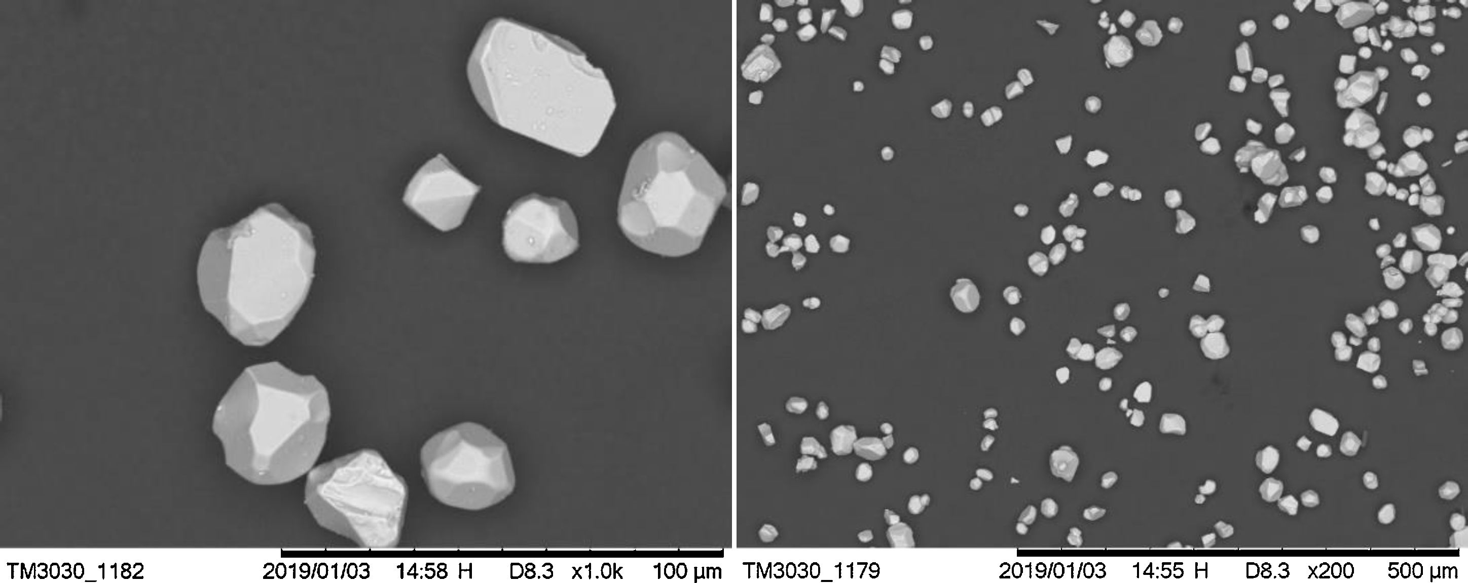
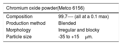
Experimental details, materials and methodsIn this study, commercially available powder (Metco 6156) was used as the coating material. Fig. 1 shows the morphology of the as received powder under scanning electron microscope (SEM) with particle sizes in the range of -35 to +15μm. The feedstock powder was manufactured by sintering and crushing and screened which resulted to blocky and smooth particles with irregular and angular shapes.

Table 1 Shows the characteristics of the as provided feedstock powder.
The chemical composition of the as received feedstock which is shown in Table 1 gives the percentage constitution as provided by Metco. Clearly, this feedstock of chromium oxide has 99% purity with other additives alloy elements.
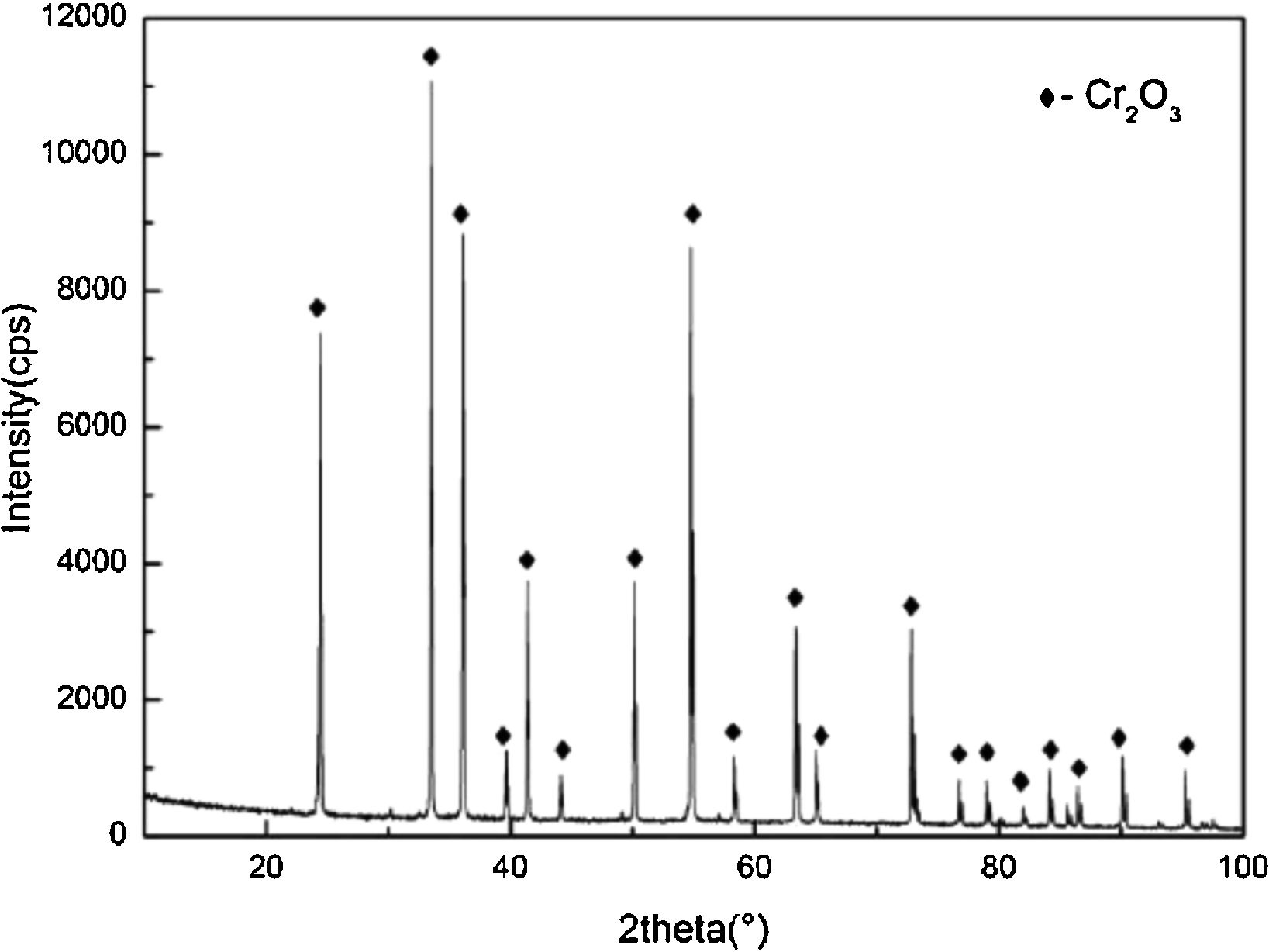
Atmospheric plasma spraying system was used to deposit coatings without pre-depositing bond coat. The chemical composition for the powder was confirmed by an EDX analysis as pure, as is displayed in Fig. 2.

The substrate used in this work was a commercially available plain carbon structural steel grade (Q235B), equivalent of ASTM A36 (Bal.Fe-0.20C-0.35Si-1.40Mn-0.045P-0.045P) which is commonly used in construction and engineering welded structures. In the Chinese market, it is commonly used in building construction and marine structures for example, in boilers, containers, connecting rods, ferrules, brackets and high voltage transmission towers, etc.[25]. The substrate dimensions which were used in this work: 10mm × 10mm × 5mm, 20mm × 20mm × 5mm, 35mm × 35mm × 5mm and 42mm × 30mm × 5mm.
Substrates were cleaned ultrasonically in an alcohol bath to remove grease and dirt thereafter grit-blasted on one side before deposition of the coating. Corundum, grit size of 40#-80# mesh was used to roughen the surfaces and the mean roughness of the substrate after grit blasting was in the range of 2.5 to 3.0μm, this was confirmed by a surface roughness tester.
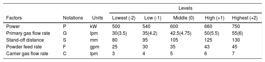
A commercial APS Thermal Coating System (UniCoatProTM with JAM-1040 junction and monitoring unit, TWIN-140 powder feeder and F4-MB-XL-6mm spraying gun, controlled by a robot IRB 1400, Sulzer Metco Switzerland) available at Shanghai Maritime University, China, was used to deposit coating with thickness of 150-200μm. The spray parameters considered are shown in Table 2 from previous documented works [22] and our laboratory studies[26,27]. The predominant factors contributing significantly on the performance of APS chromium coatings were found to be spraying power/Current (P in Kw, A), gas flow rate (Primary and Secondary, here denoted G in lpm), standoff distance (S in mm), powder feed rate (F in gpm) and carrier gas flow rate (C in lpm). The above named spray process parameters greatly influence the microstructural properties of any coating and hence its application. It is therefore paramount to find optimum levels of these variables to achieve optimal characteristics of the coatings in terms of hardness, low porosity, good adhesion properties and reduced corrosion prevalence. Different combination of APS spray parameters were used during the trial runs. The criteria for working limits were reached at by ensuring the absence of coating defects like unmelted powder particles, cracks, and large porosity, poor adhesion on the coatings and solidified inclusions within the columnar crystals. The torch was operated by a robot arm with a constant speed of 1000mm/s and the meander spacing at 6mm. Carrier gas rate was maintained constant at 4.0 l/min at a pressure of 0.30Mpa. Preheating was done by two cycles before spraying. Sample cooling were realized by two compressed air jets with constant pressure of 4 bars a nozzle diameter of 3mm parallel to the plasma plume. Table 2. Shows the process parameters that were used during optimization.
Process parameters.
| Levels | |||||||
|---|---|---|---|---|---|---|---|
| Factors | Notations | Units | Lowest (-2) | Low (-1) | Middle (0) | High (+1) | Highest (+2) |
| Power | P | kW | 500 | 540 | 600 | 660 | 750 |
| Primary gas flow rate | G | lpm | 30(3.5) | 35(4.2) | 42.5(4.75) | 50(5.5) | 55(6) |
| Stand-off distance | S | mm | 80 | 95 | 105 | 125 | 130 |
| Powder feed rate | F | gpm | 25 | 30 | 35 | 43 | 45 |
| Carrier gas flow rate | C | lpm | 3 | 4 | 5 | 6 | 7 |
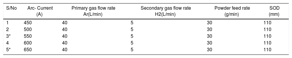
Table 3 shows the adopted spray parameters conditions.
Spray parameters after optimization.
| S/No | Arc- Current (A) | Primary gas flow rate Ar(L/min) | Secondary gas flow rate H2(L/min) | Powder feed rate (g/min) | SOD (mm) |
|---|---|---|---|---|---|
| 1 | 450 | 40 | 5 | 30 | 110 |
| 2 | 500 | 40 | 5 | 30 | 110 |
| 3* | 550 | 40 | 5 | 30 | 110 |
| 4 | 600 | 40 | 5 | 30 | 110 |
| 5* | 650 | 40 | 5 | 30 | 110 |
Key: * The samples that were considered in the discussion of for this work.
The microstructure and composition distribution of the coatings were characterized by scanning electron microscopy (SEM, Hitachi TM3030, Tokyo, Japan) and Energy-dispersive X-ray spectroscopy (EDS, Oxford Swift 3000, Oxford, UK). The phase composition of specimens was analyzed by X-ray diffraction (XRD, Rigaku Ultima IV, Tokyo, Japan) with Cu-Kα radiation (λ= 1.54 A) operated at 40kV and 20mA. The diffraction angles (2θ angle) was set in the range from 20° to 100°. The microhardness of the coatings (Vickers scale) was measured using HXD-100 TMC/LCD Microhardness tester (Shanghai Taiming Optical Instrument Co, China) on the polished cross-sections using an indentation load of 300g with a dwell time of 15s and an objective magnification of X40..
Adhesion bond strength investigation was done in accordance to the procedure from ASTM C633 standard. The tests were accomplished using a portable BGD digital pull-off adhesion tester. This tester measures the amount of tensile force required to pull-off a coating of specified dimensions from the substrate using hydraulic pressure. The pressure is displayed on a digital LCD and represents the coating's strength of adhesion to the substrate. It evaluates the adhesion (pull-off strength) of coating by determining the greatest tensile pull-off force that it can bear before detaching. The recorded results represents averages from five measurements for each kind of coating.
The coated samples were prepared for constant load scratch test. Surfaces of each samples were subjected to sliding wear tests on a pin-on-plate configuration type against tungsten carbide (WC) counter body (pin). 35μm stylus was used on a Universal mechanical Test (UMT TriboLabTM) platform. 50N load was used at constant set velocity of 5 m/s for a period of 900s with a reciprocating stylus configuration movement. The two coatings 550A and 650A sample were used in the friction test. The substrate was also used to compare the scratch test of the two coatings. The procedures were carried out in ambient air, at 25? room temperature and 45% humidity.
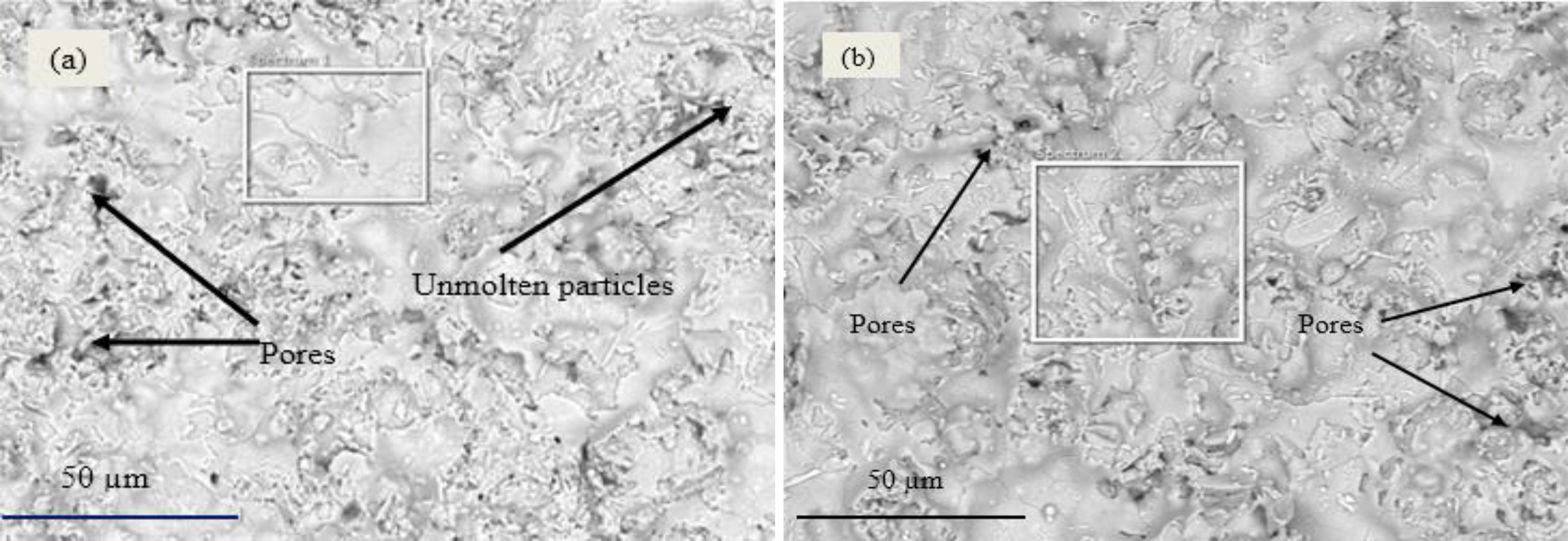
Results and discussionsMicrostructureThe microstructures of coatings 550A and 650A investigated are as in Fig. 3(a) and Fig. 3(b). The microstructures consisted of spreading splats forming lamella structures with intermediate oxide layers. Pores, cracks, inclusions, unmolten and semi molten particles were observed which are typical for a microstructure coating prepared by atmospheric plasma spraying. More pores, cracks and unmolten particles were prevalent for 550A coating than for 650A coating. Lower spraying current for 550A coating, occasioned less heat to completely breakdown the powder particles during the plasma stage. This led the spraying plume to consist of unmolten and semi molten particles. As subsequent layers are formed, interlocking between unmolten particles led to formation of pores and regions of unmolten particles. For the case of coating 650A, there was fully molten feedstock. This necessitated homogenously spreading lamella structure. The presence of pores and unmolten particles was less for this case. There were some microcracks that could have resulted from residual stresses during solidification and cooling.
 550A coating (b) 650A coating.")
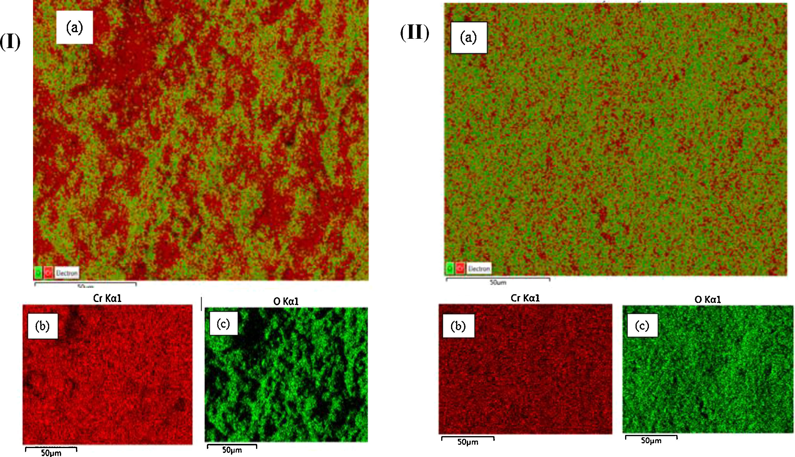
Porosity evaluation of SEM micrographs for the two coatings was carried out by image analysis using ImageJ software. Coatings 550A (Fig. 3a.) had porosity of 8.% with bigger pores and irregular in shape. Coating 650A (Fig. 3b.) had porosity of 4.%, predominantly nearing the edges. The main base layer for both coatings was Cr as can be seen from EDS layered images in Fig. 4(I) and Fig. 4(II). From fig. 4(I) for coating 550A, two distinct layer can be clearly seen. The Cr layer forms the base of coating. O layer comes in between the Cr layer and gives a vivid representation how coating occurred. Irregular surface appeared which caused interlocking of layers hence porosity was evident. Fig. 4(II) shows EDS layered image for coating 650A which is more homogenous, with Cr as the base layer and O as the top layer. It is evident that both layers completely cover the whole substrate surface with very few discontinuities compared to the case of coating 550A.
 550A and (II) 650A;(a) combined layer (b) Cr (c) O.")
Porosity has a direct correlation with the tensile bond strength and hardness of the coating. Coating is known for its hard coatings which is commonly used for wear and abrasive protection.
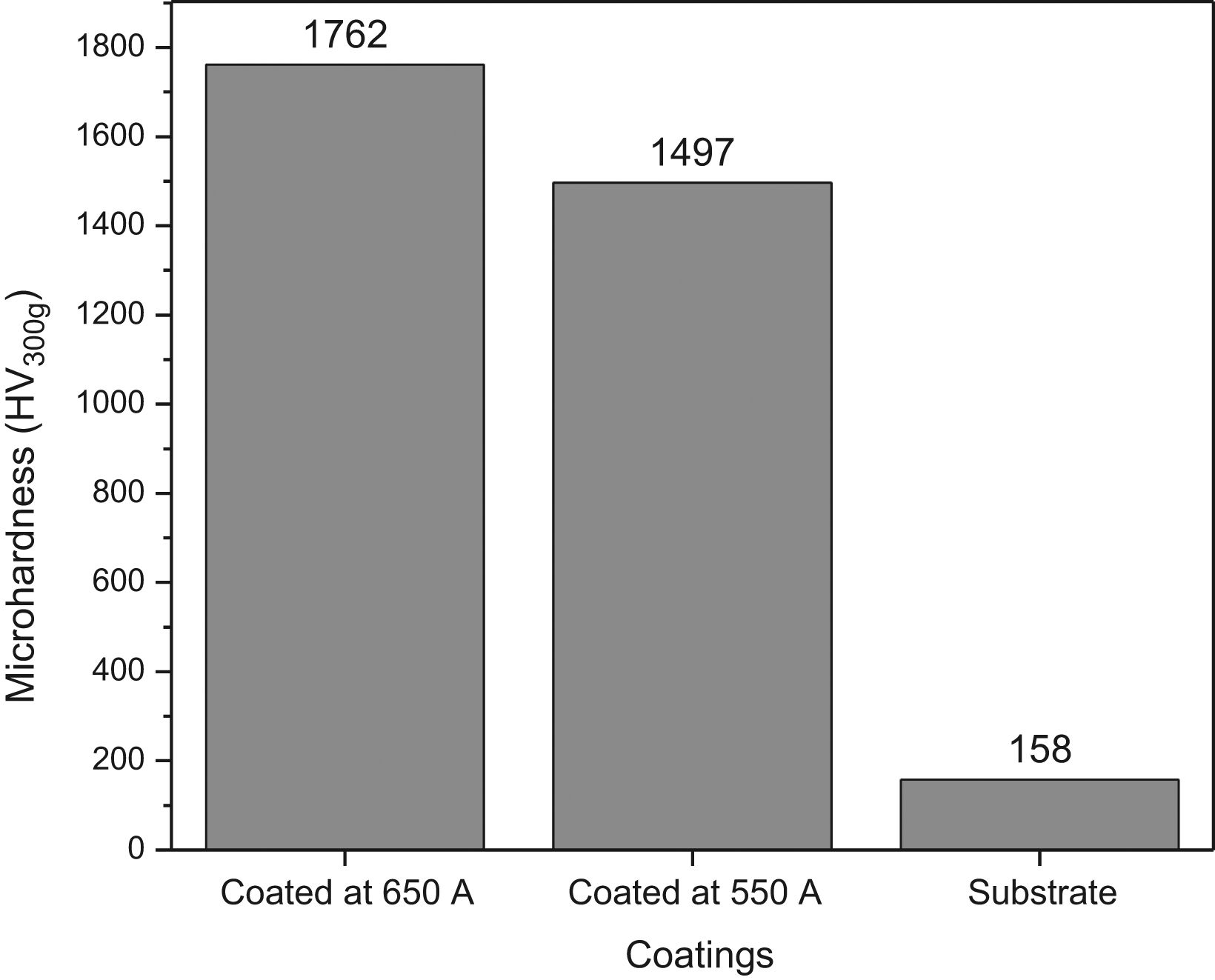
The microhardness and indentation examination was carried out on the cross-sectional surface of the coatings. The cross-sections were first prepared by polishing and cleaning to remove any dirt ensuring no damage to the coatings. Lower indentation loads were chosen which could not initiate cracks or micro-cracking on the in prints at the edges of the coating surface [28], this was to ensure results obtained were reliable. A HXD-100 TMC/LCD Microhardness tester was used to get the microhardness values of the coatings. A load of 300gf was used with a 15seconds dwell time. Vickers microhardness values were taken and average values for each sample is illustrated in Fig. 5. Vickers microhardness values for the sprayed coatings 550A and 650A are 1496 HV300g and 1762 HV300g respectively. From earlier discussion, 550A had a higher porosity level of 8. while 650A had 4. There is a relationship between the presence of pores and microhardness of a coating, it has been argued that presence of pores in a coating provide weak sites where particle bonding could be weakest [29]. These gives way during any small load application on the surface coating hence compromising on the integrity of the surface quality in terms of its hardness. In cases of abrasion wear, pores can also act as the points wear fractures starts. Regardless of variation between the hardness values for coatings 550A and 650A, their values were 10 folds that of the substrate. Figure 6

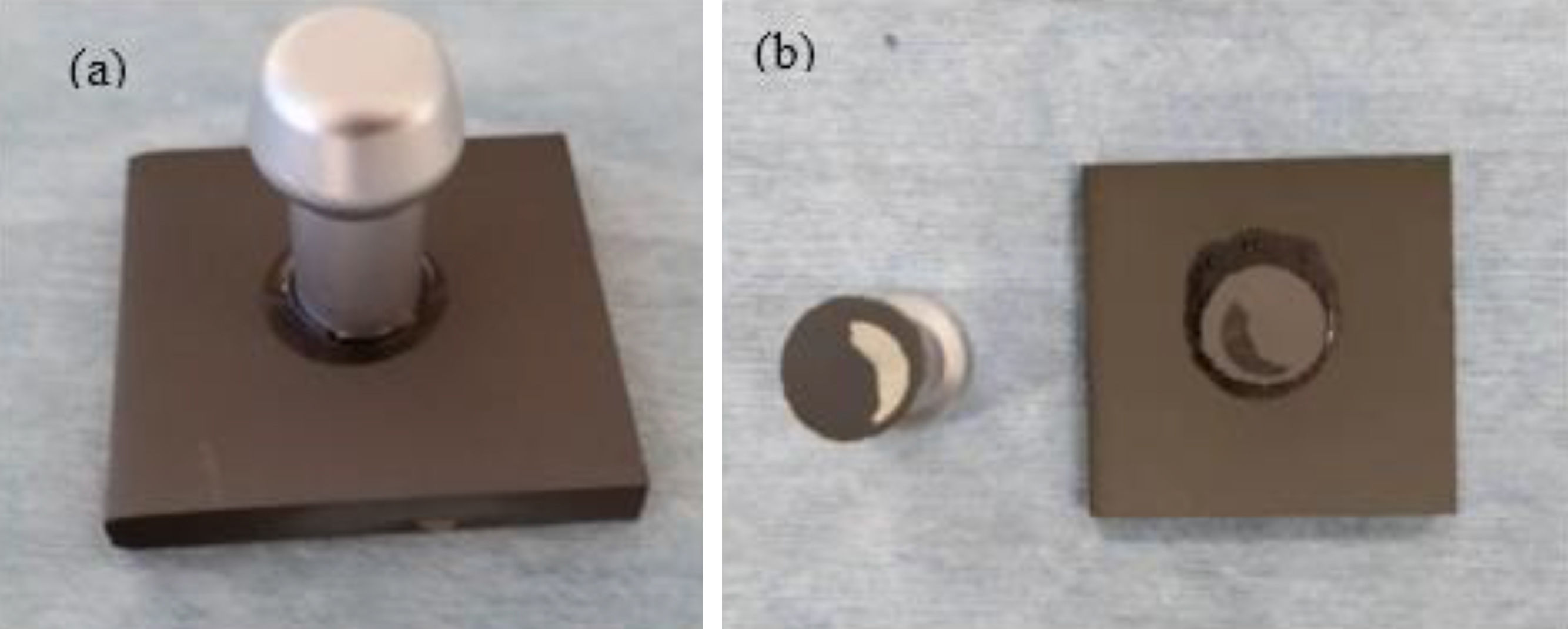
 Dolly glued to the coating surface (b) dolly separated from the coating. Showing part of the coating left on the dolly while the other part left on the substrate.")
The bond strength for coating/substrate interface was measured using pull-off adhesion method. The final bonding strength values were taken from the average bond strength after taking several measurements for two samples tested under the same conditions. Fig. 7 shows work piece before and after the tensile bond strength test. A small section of the coating remained glued to the dolly while the other part remained on the substrate. This was a typical adhesive failure mode as prescribed by ASTM C633 standard [30]. There was a fracture between the coating/substrate interfaces, with no indications of fracture between the layers of coatings.
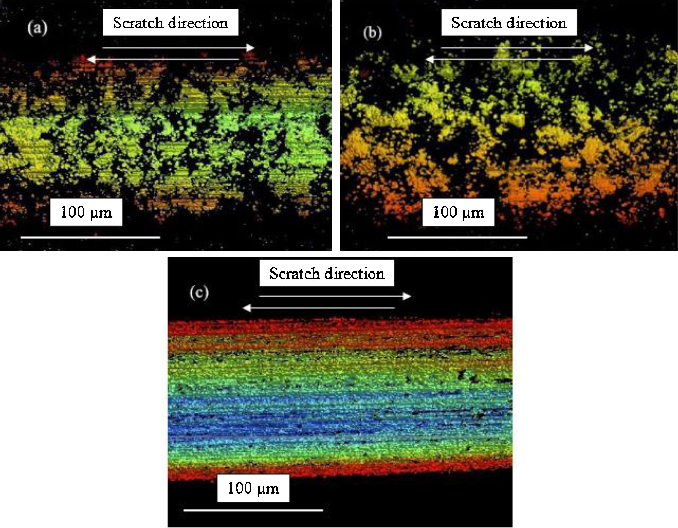
 coating 550A (b) coating 650A and (c) Substrate after scratch tests in ambient dry conditions using constant load.")
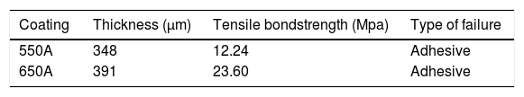
Table 4 gives a summary of the results indicating the averaged bond strengths and the mechanism of failure encountered.
It is apparent that the bonding strength of the coatings increased with the increase in spraying current. This is because, increasing the spraying current increases the temperature of particles within the plasma region.
Figure 4 Adhesion/cohesion testing pieces (a) before (b) afterThe high temperature guarantees complete melting of powders leading to uniform coating with fewer pores, hence low porosity. This is evident from porosity results. Besides, well bonded and densely coated surface gives a higher tensile bonding strength compared to one that has a larger percentage of porosity[29]. Porosity is one of the parameters that influence the tensile bond strength of a coating. It is in agreement that a coating with higher porosity level; 550A coating had a lower bonding strength. The presence of pores and unmelted particles act as weak spots for the commencements of fracture and its propagations. Table 4 gives a summary of the results indicating the bond strengths and the mechanism of failure encountered. Figure 8
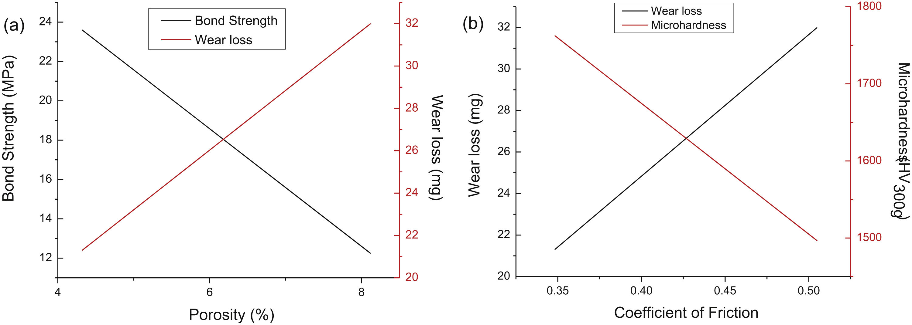
 Bond strength and wear loss against porosity (b) Wear loss and microhardness against coefficient of friction.")
Fig. 9 show the amount of wear loss for the two coatings 550A, 650A and substrate metal for a constant normal load of 50N in dry ambient condition. The amount of wear loss was highest for the substrate and lowest for 650A coating. It is evident that coating provided a wear resistant protection for the base metal. For the cases of the two plasma sprayed coatings for, coating 650A performed better than coating 550A. The previous discussions regarding hardness and porosity level also agree with the tribological characteristics that a harder surface with lower porosity percentage provides a better wear resistant coating.
Comparing the two coatings 550A and 650A, wear products (particles) found between the coatings and the counter body (WC) played a big role in propagating more wear on the coating. It was found that as debris were released from the coating surface, some got embedded, welded on the counter body and moved along with the stylus to cause further wear. This agrees with the previous findings that any debris or loose particles on the surface of a coating could necessitate further abrasion and erosion on the surface of any coating [31]. This is particularly true where porosity level is high. The presence of pores could provide weak notches from which fractures are initiated from. Harder surfaces, 650A with less pores had low wear loss.
Fig. 11 describes the friction coefficient variations against the two coatings 550A and 650A compared with that of the base metal in dry ambient environment under constant load. With load constant, the friction coefficient values were recorded for period of 600seconds. The best line of fit was used to obtain the values of coefficient of friction for the three samples. The substrate had the highest value of friction coefficient of 0.6778, followed by coating 550A with 0.50498. Coating 650A, had the lowest value of friction coefficient of 0.34815. The friction coefficient values for coating 550A was higher than for 650A, denoting that there was more friction on 550A because of the presence of pores and unmolten particles. This resulted to plastic deformation of the coating surface. The abrasion products together with further scraping of the surface led to higher values for friction coefficient. It is clear that the two coatings had better wear resistance compared to the substrate metal. Additionally, as it is evident from fig. 10, the amount of wear loss for coating 550A is higher compared with coating 650A. Apparently the erosion was higher for softer coating and the wear products played a major role to further the abrasion activities.
Optical microscopy images observations of the worn-out samples which were tested under ambient dry conditions are presented in Fig. 12. The occurrences of smooth tracks on the surface of the substrate, (Fig. 12 c.) indicates that there abrasion was highest. Subsequent wear particles which were embedded on the counter body's tip continued to abrade the surface hence the appearance as seen on the optical microscopy images. For 550A coating (Fig. 12 a.), it was observed that the surface topography had the most deformation comparing the two coatings.
The eroded surfaces depicted uniform scraping off of the coating surface which was further aided by wear products as the cycle of loading continued. There was plastic deformation accompanied with delamination of the coating. It has been argued elsewhere in literature that high level of porosity facilitate abrasion wears but in the same instance reduces any excessive internal stresses to subsequent layers of coating [32]. For 650A coating (Fig. 12 b.), it was observed that failure mechanism was more of chipping since the coating surface was harder compared to the 550A coating. This occurred with the increasing number of loading cycles. Plastic deformation is common with hard surfaces and as evident from the images, not the whole length of the sample was scraped off. For the substrate surface (Fig. 12 c.), there was uniform deformation that started as elastic but gradually changed to plastic deformation with increase in loading cycles.
Correlation of the results and the discussionFig. 13 depicts the relationship that bond strength and wear loss has in regards to the porosity of a coating. Coatings 550A and 650A have been analysed in the proceeding discussions with percentage porosities as 8% and 4% porosity respectively. As the porosity of coating increases, the amount of wear loss increases. Porosity presents weak sites and in the instances of frictional forces, more material from the surface of the coating is detached via abrasion. Bond strength and porosity have an inverse relationship. Coating with higher bond strength have lower porosity level and vice versa. This is because high bond strength coating means that the coating surface has closely packed and securely bonded elements that form the coating. To separate such a coating from the substrate, a higher tensile force is desirable. Fig. 14 represents the correlation that wear loss and microhardness has with respect to the friction coefficient of coating (550A and 650A). It was observed that as friction coefficient (COF) increases wear loss also increases while in the same instance microhardness reduces. A coating with lower COF had higher microhardness value with least amount of wear loss. The reason is the same as discussed above, coating surface that is compact with high bonding strength is hard to abrade hence higher hardness value. Such a coating has the best wear resistance properties.
ConclusionA set of coatings were prepared by atmospheric plasma spraying varying the spraying current with gas flow rate (primary and secondary gases), powder fee rate and standoff distance all kept constant. From the study we concluded that varying the spraying current affected the microstructure, microhardness and tribological characterization of the coatings. The following findings can be derived from the work:
Microstructural observations showed the presence of pores, microcracks, unmolten and semi-molten particles on the coatings. The amount of defects observed on 550A coating were higher than for 650A coating. As assigned earlier, 550A coating and 650A coatings represents coating prepared when the spraying currents were 550A and 650A respectively. The microstructure was more compact and well layered when a higher spraying current was used.
The corresponding microhardness value obtained for 650A coating, 550A and substrate were 1763HV, 1497HV and 158.HV. Microhardness values increased with increase in spraying current which necessitated a better compacted coating with lower porosity percentage. Moreover, the bond strengths of the coatings were also directly related to the tribological characterization of the coatings which are controlled by the spraying current.
For the case of tribological characterization, coating produced under higher spraying current experienced the least wear loss with the best frictional resistance capabilities. Wear losses gradually increased with the reduction in spraying current.
FundingThis work was supported by the National Natural Science Foundation of China Grant No. 51572168
The authors would like to acknowledge Prof Wei Haijun and Mr. Li Hong of Tribology and Oil analysis laboratory of Shanghai Maritime University, where we carried our tribology exercise.

