

Recently built for the Bus-HOV lane on the C-58 Motorway, the Viaduct consists of an elevated structure, the piers of which are located in the space between the two decks of an existing viaduct.
The new deck consists of a spatial steel tubular structure that supports a concrete platform, on which the carriageway runs.
Unknown for this type of structure, the design of the construction system involved erecting the piers and deck 100% without the support of the existing viaduct decks which were only occasionally used for auxiliary aid jobs, control and inspection so that traffic was not cut off at any time.
El viaducto recientemente construido para el carril Bus-Vao en la autopista C-58 está constituido por una estructura elevada cuyas pilas se sitúan en el espacio comprendido entre los dos tableros de un viaducto existente.
El tablero del nuevo viaducto está formado por una estructura metálica espacial de tubos que soporta una plataforma de hormigón sobre la que discurre la calzada.
El sistema constructivo desarrollado, inédito para este tipo de estructura, ha consistido en el montaje del 100% de pilas y tablero sin contar con el apoyo de elementos de obra sobre los tableros del viaducto existente, que tan solo han sido utilizados ocasionalmente para labores auxiliares de ayuda, control e inspección, de tal forma que en ningún momento se ha precisado cortar el tráfico de vehículos.
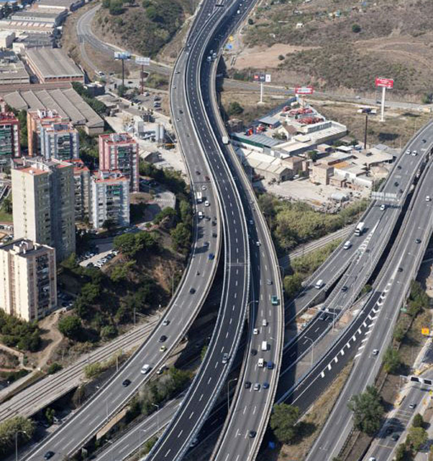
The C-58 Motorway, for access to Barcelona from the Northwest, accumulates one of the heaviest traffic peaks in Catalonia (150,000 vehicles a day in 2011), often causing traffic to collapse.
In order to reduce traffic congestion in peak hours, it was planned to extend the Motorway on the stretch between Ripollet (Barcelona) and the Avenida Meridiana of Barcelona, by creating a Bus-HOV lane (High Occupancy Vehicles).
The extension consisted of a new carriageway with two 3.50m wide lanes and hard shoulders measuring 1.50m. The project had to solve a complex problem caused by the difficulties stemming from the existing space boxing in the Motorway and running along two parallel viaducts, each with three lanes of traffic.
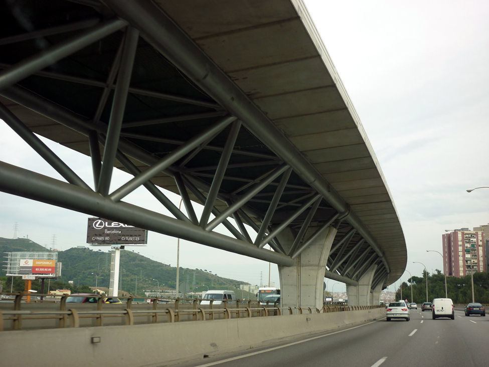
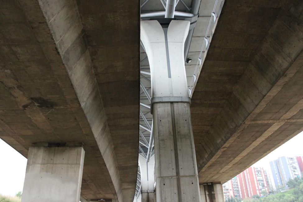
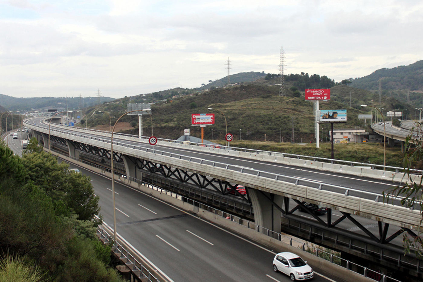
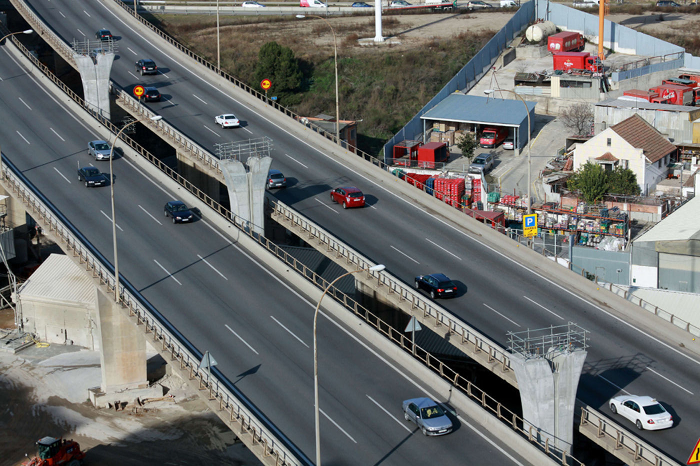
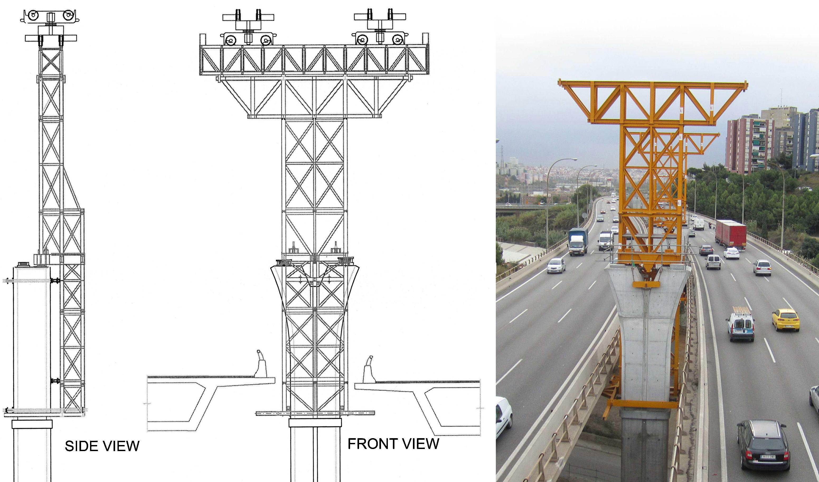
The solution that was adopted consisted of building a new viaduct forming a singular project due to its location, the deck of which runs parallel at a level above the carriageway of both viaducts (Fig. 1) and with piers that emerge from the intermediate space between the decks (Fig. 2).


The deck, which runs over the carriageways of the existing Motorway, was designed with shapes that meet the appropriate aesthetic requirements for its integration into the environment and which provide the observer with the maximum sensation of transparency.
Building the deck, which runs parallel above the carriageway of both viaducts, required designing a special procedure, which imposed a condition which consisted of dispensing with any type of lifting device over the existing decks of the Motorway because of the dense traffic.
Broadly speaking, the procedure consisted of building the structural elements of the deck and the upper part of the piers on the ground and then proceeding to assemble them into their final position using special launching systems supported by the structure itself, as it was being constructed.
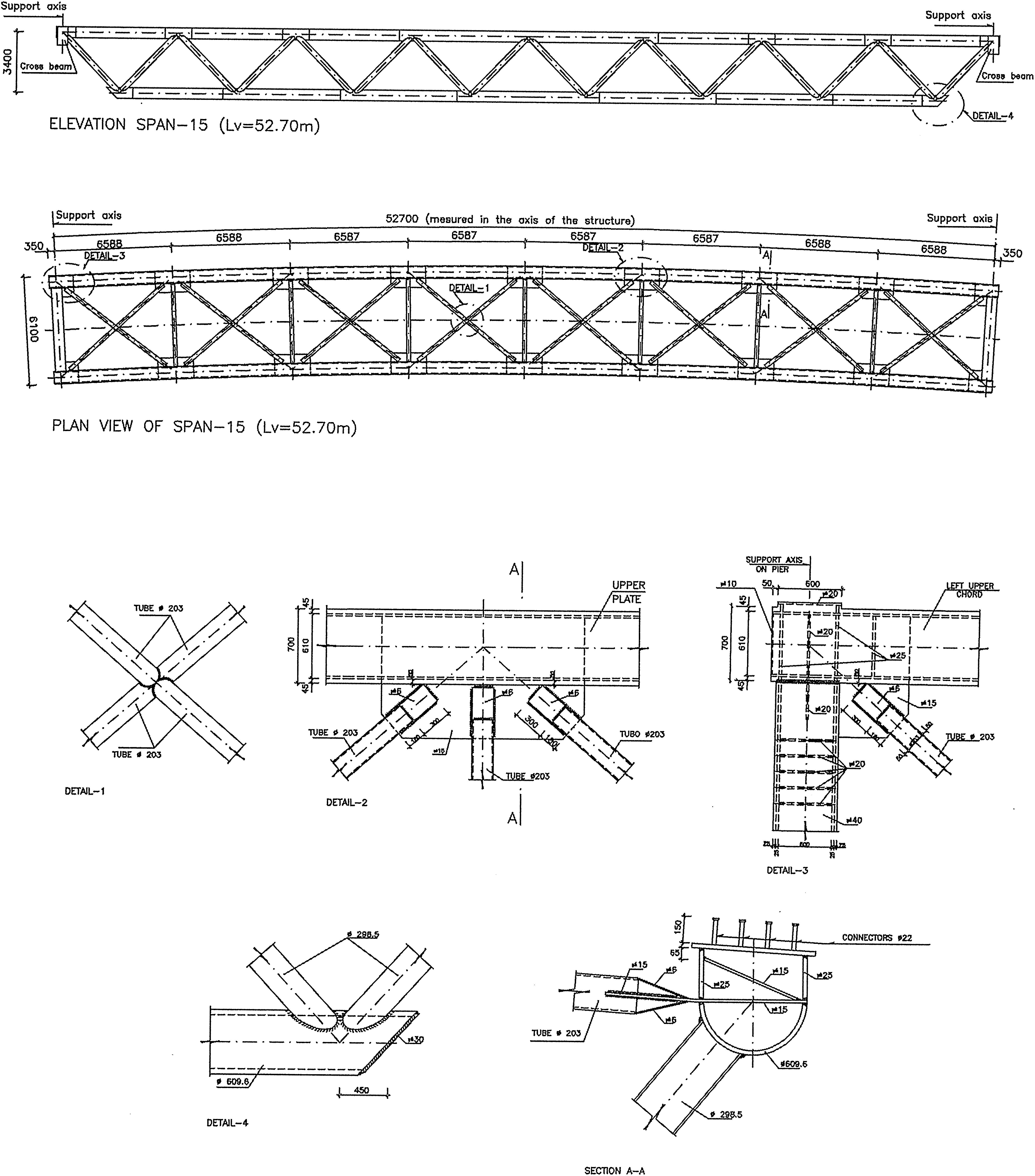
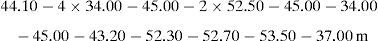
2Bus-HOV viaduct characteristics2.1General dimensionsThe viaduct has a total length of 693m and comprises 16 spans, with the following succession of spans measured between the axes of the piers (Figs. 3 and 4).


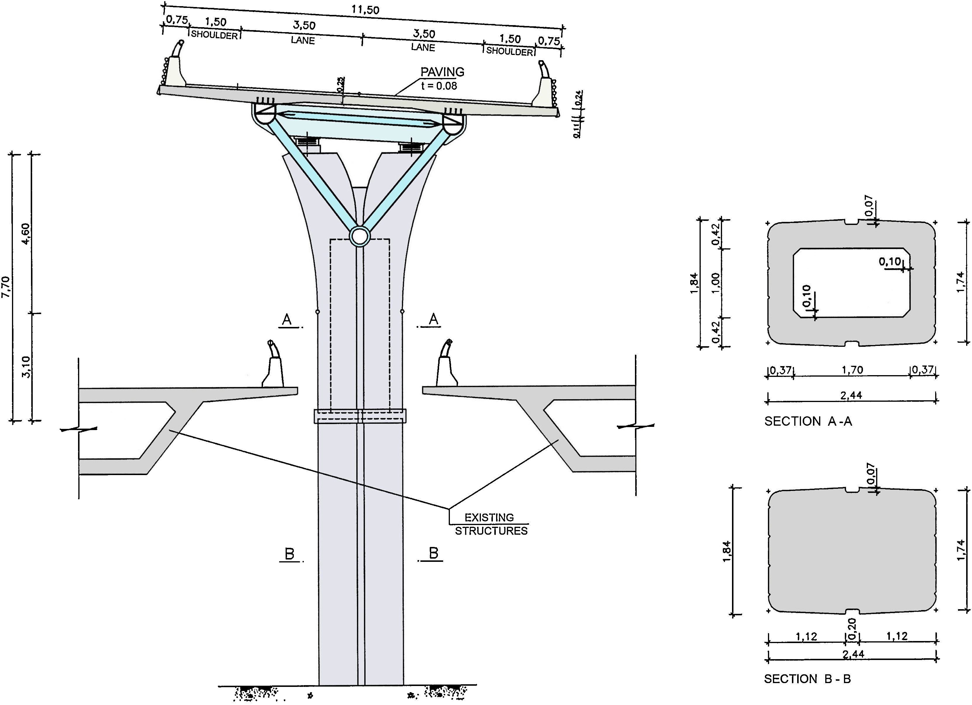
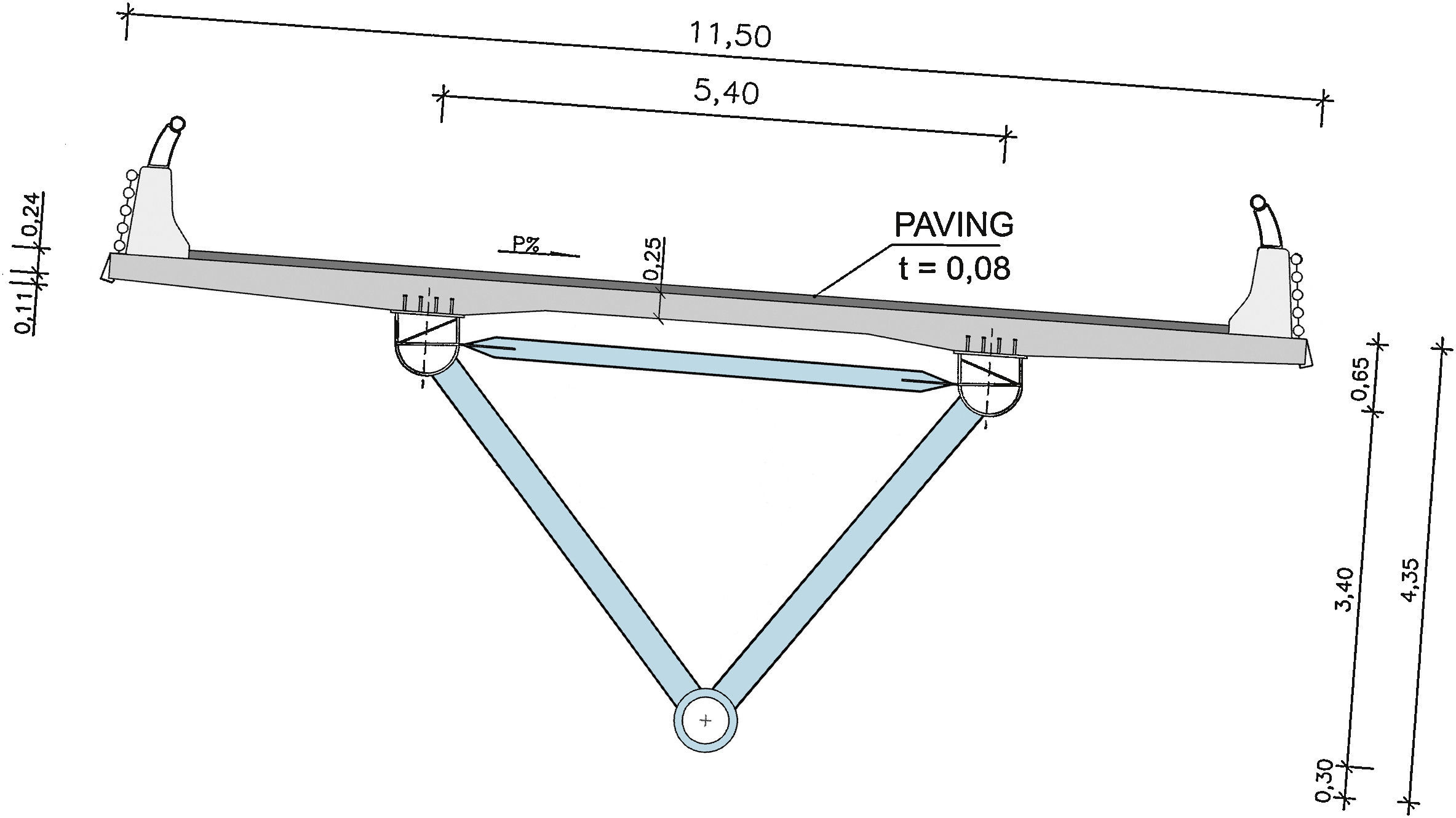
The deck has a total width of 11.50m.
2.2PiersEvery pier comprises a concrete shaft with a constant exterior section, which has an upper extension in the shape of a capital, suitable for providing support for the decks (Fig. 5). There is a total of four support devices on the crowning, two for each of the adjacent decks.

The lower part of the shaft is solid, built in situ and hollow at the top, which is prefabricated.
All the piers are sited in the space between the decks of the existing viaduct, the minimum horizontal distance of which is 3.60m; this is less than the transverse size of the capital of the pier (4.44m), where the deck supports are located.
Such a circumstance, added to the restrictions when using the existing viaduct for supporting the auxiliary construction means, was the reason behind designing a special procedure for mounting the piers completely from the ground, irrespective of the existing structure.
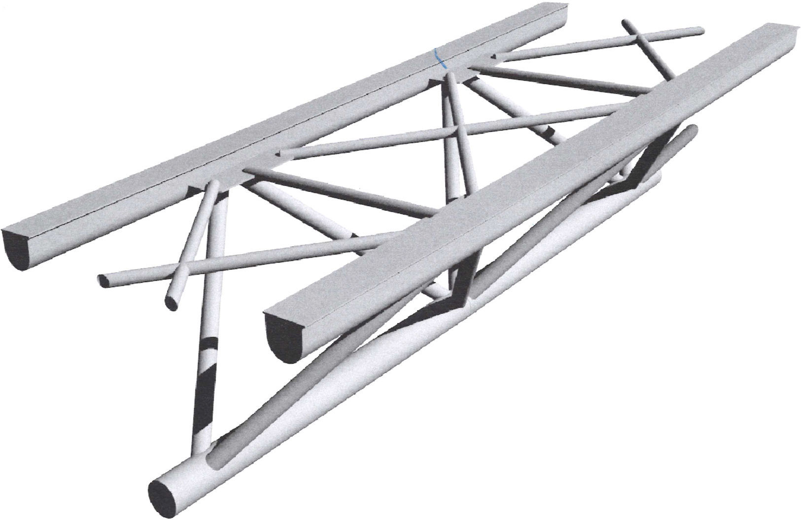
2.3DeckThe deck of the viaduct consists of a total of 16 spans with isostatic sustentation. Each span is formed by a spatial tubular structure, the upper part of which has a concrete platform, comprising prefabricated slabs joined together by means of subsequent concreting and structurally connected to the metal latticework forming a mixed steel – concrete structure.
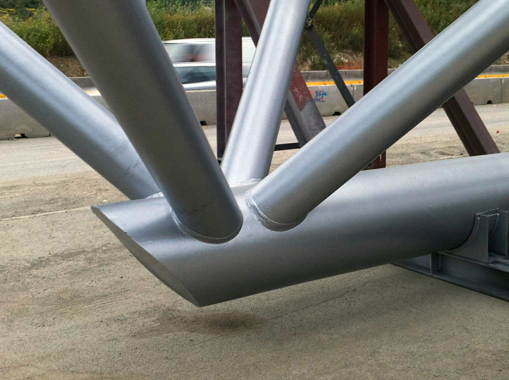
The metal latticework is formed by two upper semi-tubular chords to provide a flat surface on the top for supporting the deck slabs (Figs. 6 and 7). A single tube forms the lower chord. The main diagonals, which are also tubular, are placed as per the “Warren” scheme.


The main joints of the tubular structure were designed so that no internal transverse stiffeners were required, thus avoiding not only some difficulties in carrying out the welding on the inside, but also the need to make tie-ins in the main tubes on both sides of each joint. Fig. 8 shows details of the main and secondary joints of the upper chord, where connecting plates are placed.

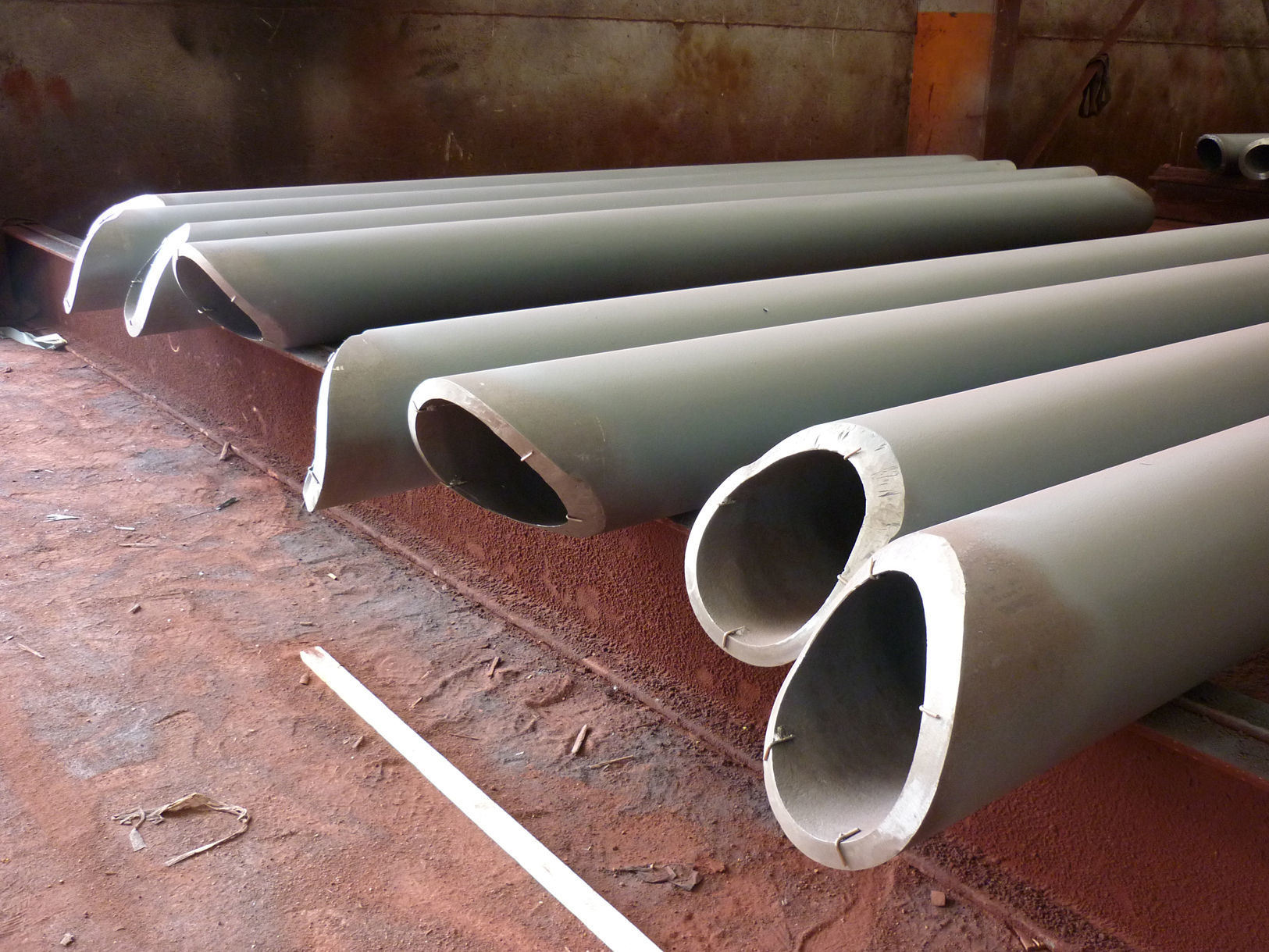
Building the metal structure in the workshop was carried out by following rigorous geometric control for the correct formation of the joints where the main diagonals meet the tubes forming the upper and lower chords (Fig. 9).

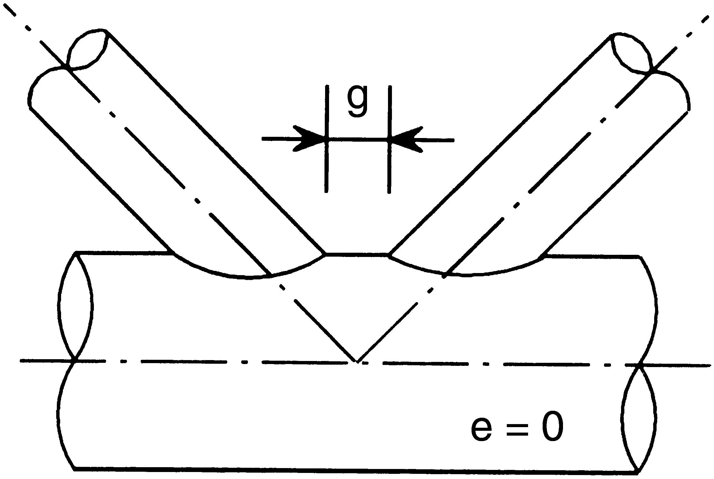
Special attention was paid to the cutting procedure, outlining their peculiar shape (Fig. 10) and to preparing the edges at the ends of the tubes forming the diagonals, so that they fit perfectly with the surface of the tubes of the main chords [1], thus guaranteeing uniform thickness of the weld beads to be applied and adjusting the “g” value of the spacing foreseen in the project (Fig. 11).

.")
The latticework was designed so that the tube axes of each of the joints converge at a point of union, thereby as there are no eccentricities when applying axial loads transmitted by the bars, no secondary bending stress occurs. Bearing this condition in mind, together with the consideration of the tube diameter forming a joint, the size of the “g” spacing is determined for every case, forming a fundamental parameter that depends directly on the efficiency of the structural capacity of the joints for stress transmission [2–6].
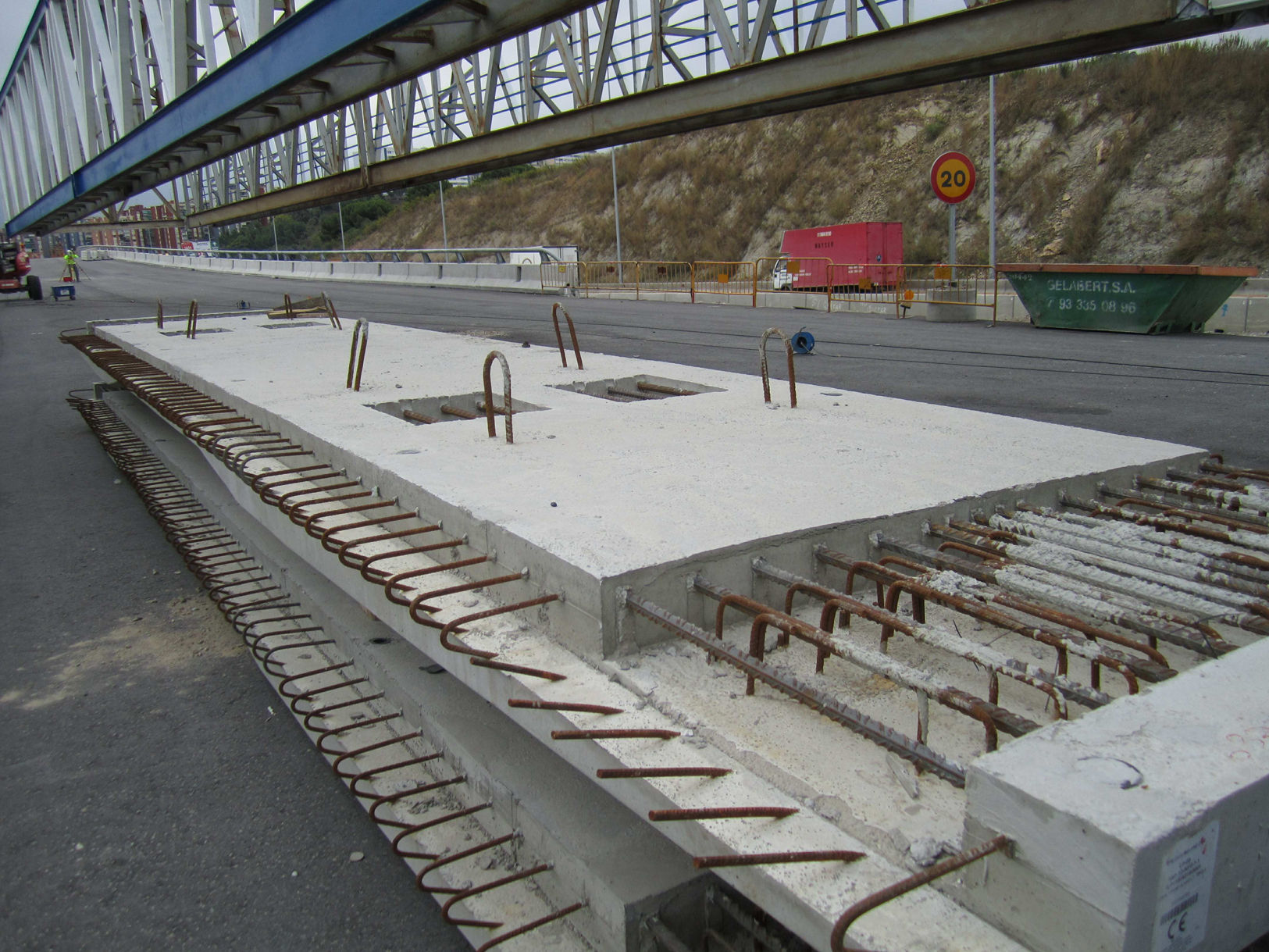
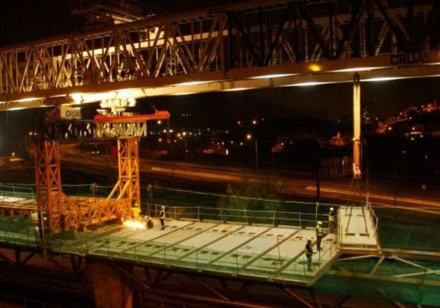
The upper platform of the deck is made of prefabricated slabs (Fig. 12), the length of which coincides with the width of the deck. These are equipped with niches for connection to the metal structure. There are spaces on both sides of each slab for subsequent filling with a special mortar after placement.

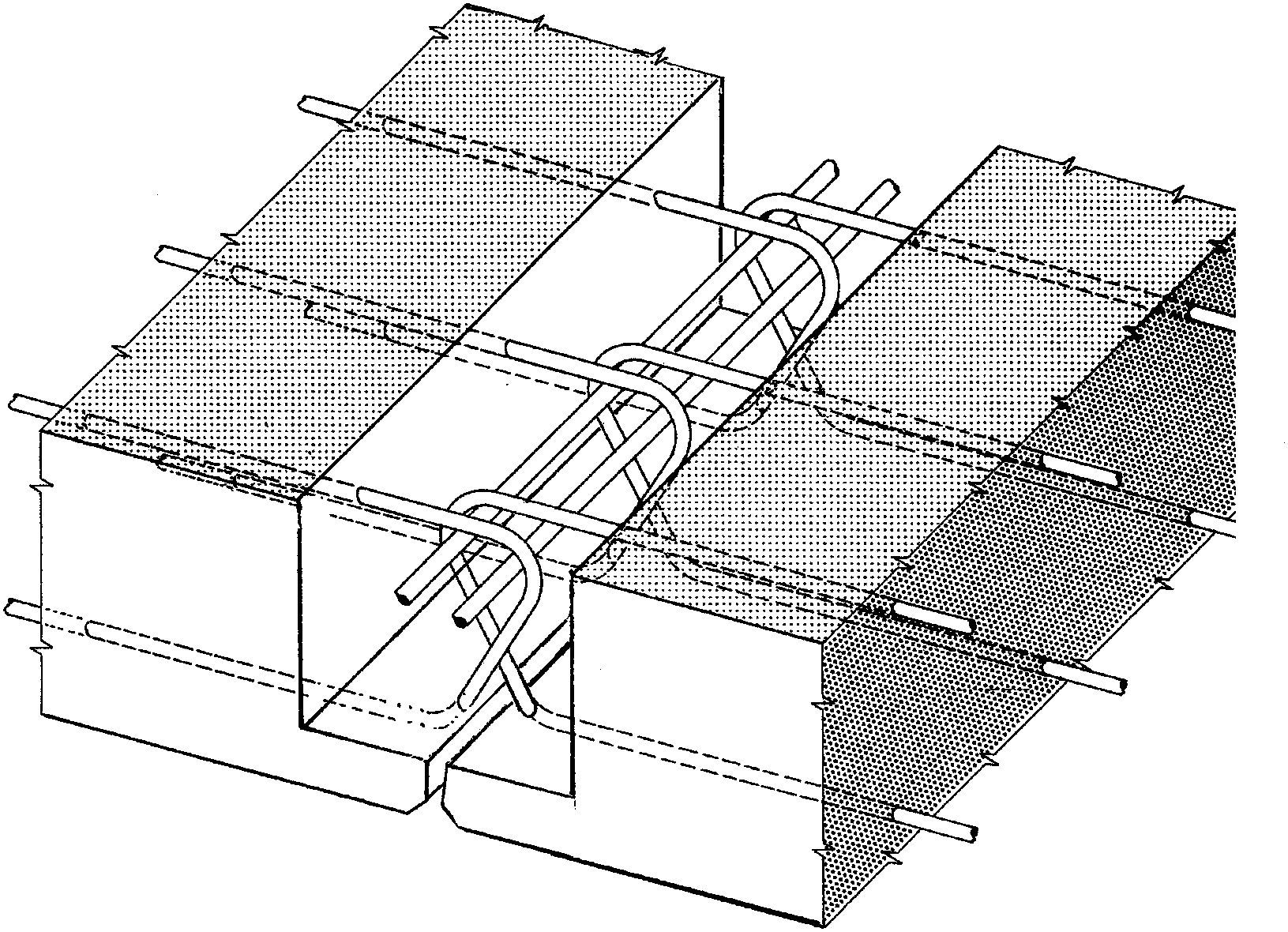
The slab reinforcement was arranged in parallel to the longitudinal axis of the deck and protruded to form the structural union between the adjacent prefabricated pieces (Fig. 13). They are 12mm in diameter and adopt the shape of a closed loop with an arrangement such that the distance between the bar axes have a minimal overlap (20mm) so as to optimize the stress transmission conditions [7].

Structural continuity is established between the contiguous deck slabs, having considered it suitable to install three expansion joints between the final ends of the deck of the viaduct in order to use only neoprene bearings with the appropriate thickness and thus avoid placing special support devices at a higher cost. The maximum distance between expansion joints is 180m and forms a stretch of deck with a constant slab in which the magnitude of the maximum horizontal movement at the ends is compatible with the transverse distortion capacity of the elastomeric bearings.
The ends of each deck rest on the piers by means of 2 neoprene pads measuring 600×400mm with a total thickness of 196mm. The size of the neoprene blocks is identical in all the viaduct support devices.
Adopting a mixed structure for the deck, with the metal fraction formed by a spatial tubular structure, provided the aesthetic qualities that are appropriate for giving a pleasant image to motorway users driving along the viaduct, located at a lower level. The magnitude of the whole depth of the deck of the Bus-HOV Viaduct (4.35m), very much more than what would have been appropriate if the deck had been made of web girders, does not disrupt the sensation of lightness. However it provides an added advantage to the structural order, due to the great stiffness as a result of bending and torsion.
The working conditions and performance of the structural materials forming the deck were favourable, thanks to the scheme used and were only penalized by a partial loss of efficiency in the unions in the joints, which is characteristic of tubular structures with no stiffeners, as well as due to the effect of fatigue [8], which is negligible in this case.
The amount of structural steel placed on site represented 225kg per square metre of deck in the widest spans (53.50m) and 175kg/sqm in those measuring 33.20m.
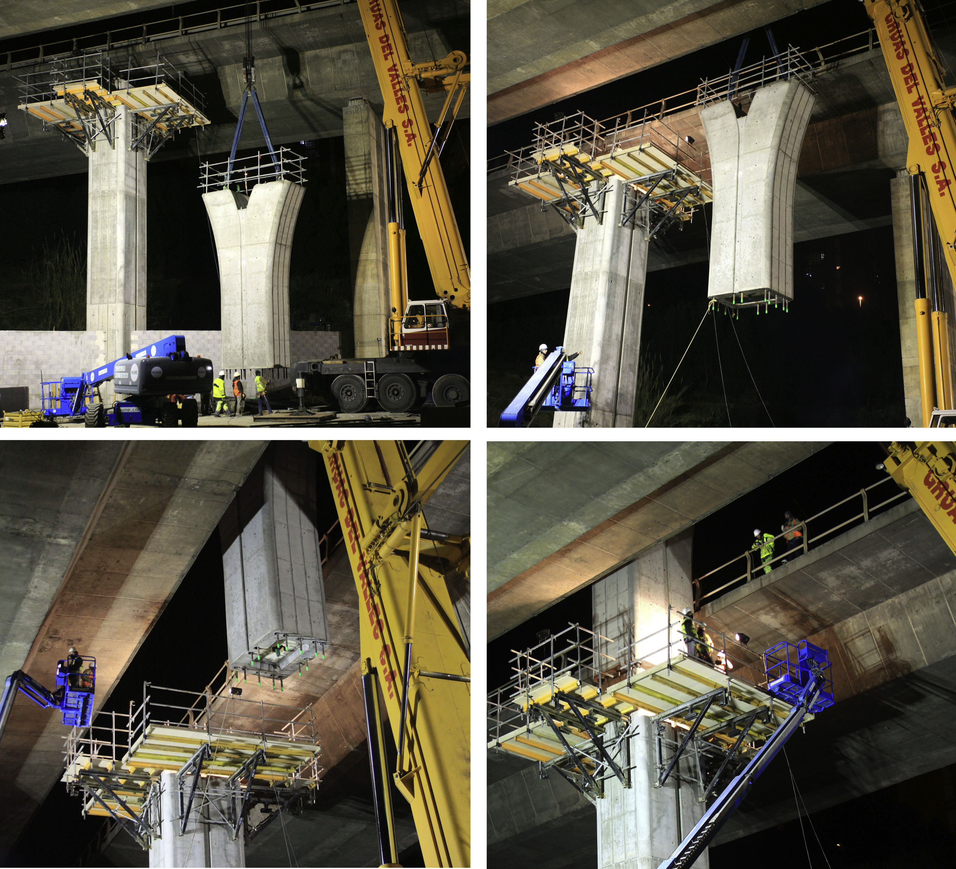
3Construction3.1PiersThe piers were built in two stages: firstly, by pouring concrete in situ using climbing formwork until reaching a height under the top flange of the existing deck. The remaining fraction of the pier was prefabricated on solid ground and then put into place with the use of a crane (Fig. 14). This procedure was designed because it was impossible to build the piers using the conventional system, which would not have been possible due to the physical proximity of the two decks of the current viaduct.

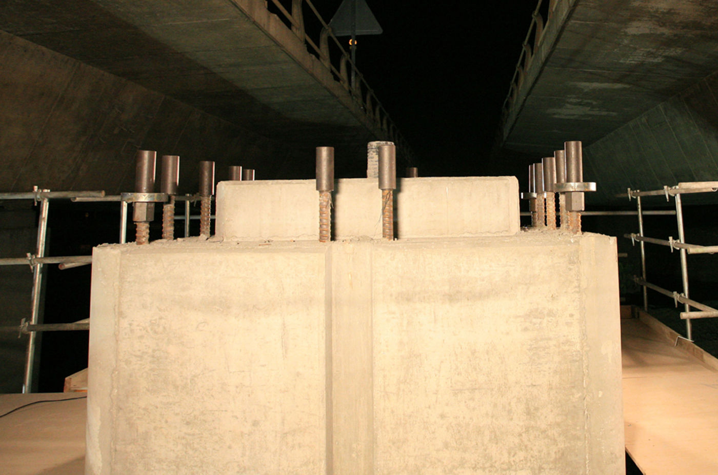
To materialize the union between the two parts forming each pier and to make it possible to mount the assembly quickly, besides the normal reinforcement of the concrete piece, a group comprising 14 threaded bars measuring 50mm diameter crossing the area of the union and forming a single reinforcement were installed to withstand the stress during the service stage in the intermediate section between the fraction built in situ and the prefabricated piece.
The said bars were built into the concrete at the bottom of the pier, constructed in situ and they protrude at the top (Fig. 15).

Upper part of the fraction of pier built in situ. You can see the 50mm diameter vertically protruding bars placed prior to the operation for mounting the upper prefabricated piece. Compression nuts on the corner bars and bearing pads are placed below the couplers. Only stress bar couplers were placed on the remaining bars.
On the upper fraction of pier, formed by the prefabricated piece, the bars are placed inside some metal ducts that are grouted once the prefabricated piece has been placed in its final position. Couplers are used to make the union between the bars of the two parts.
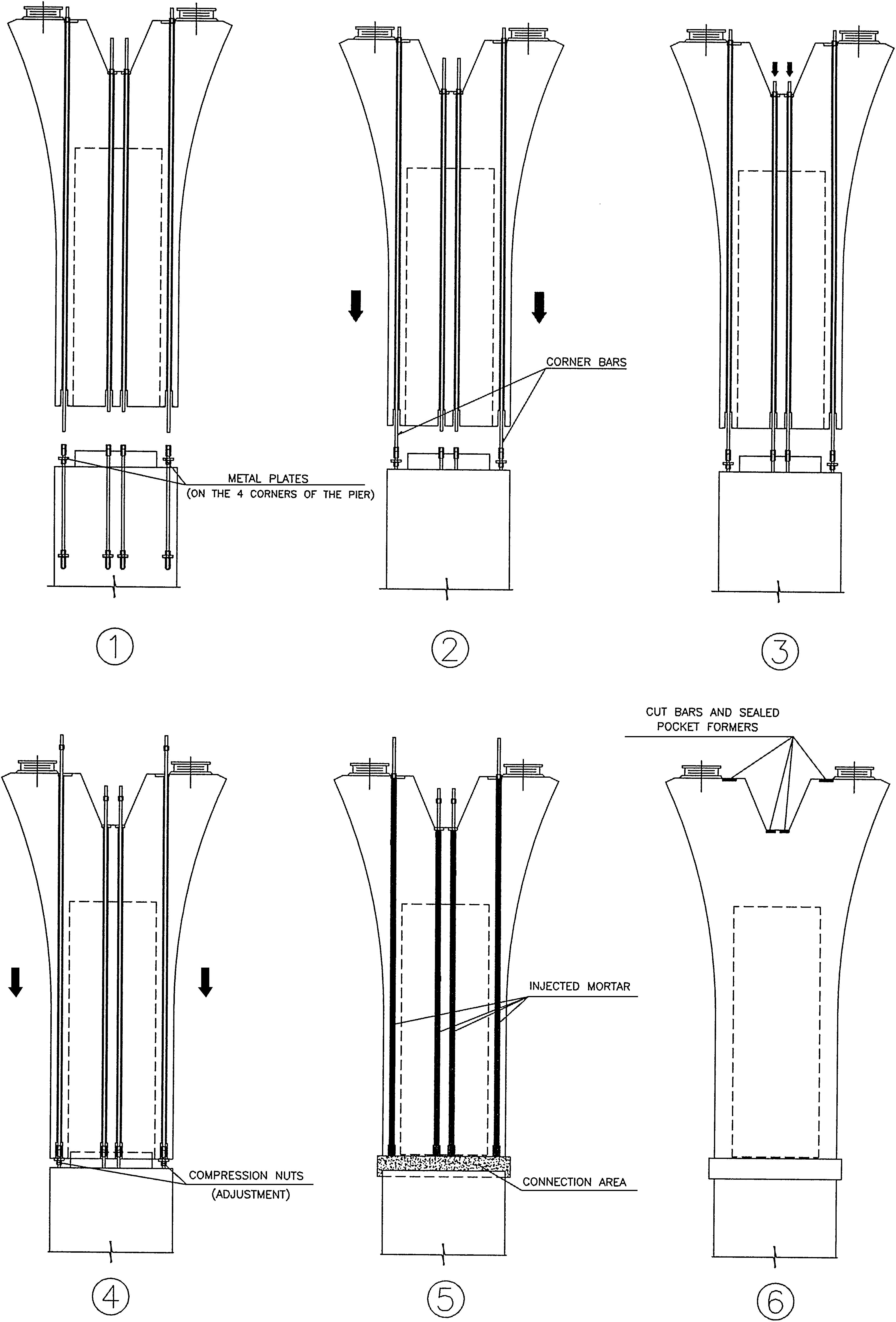
Fig. 16 shows the stages and details of the procedure for mounting the upper prefabricated part.

Description of the assembly stages of the upper fraction of the pier:
- 1.
Placing of compression nuts and metal plates to support the 4 bars located on the corners of the pier, below the couplers.
Placing of only couplers on the remaining bars.
The bars belonging to the prefabricated piece, placed inside the metal ducts, are fastened to the crowning using the relevant retention nuts. The 4 corner bars have a longer salient length, on the lower part, compared to the others.
Elevation by crane of the upper prefabricated fraction of the pier, turning the piece according to the vertical axis and positioned it onto the lower fraction.
- 2.
Controlled descent of the upper prefabricated piece and connection of 4 corner bars using the relevant couplers.
- 3.
The position of the upper prefabricated piece suspended from the crane is maintained.
Descent of the remaining bars by turning the retention nuts located on the upper part of the prefabricated piece.
Connection of the said bars by means of the relevant couplers.
- 4.
Slow descent of the upper prefabricated piece until achieving contact with the metal plates of the 4 corner bars.
Verification of the verticality and contract adjustment of the 4 plates by turning the compression nuts. Once verified, the bars are adjusted by tightening the nuts of the corner bars placed on the upper facing of the prefabricated piece.
From then on, the unit is stable and released from the crane.
The prefabricated piece still rests exclusively on the plates of the 4 corner bars and is anchored to the upper part. There are no stability problems in the compressed fraction of the 4 corner bars that support the weight of the prefabricated piece due to the short length of buckling (35cm).
The above assembly operations were carried out at night for safety reasons. The maximum time recorded on site for assembling each prefabricated piece was less than an hour and a half.
Once the prefabricated piece was mounted, the following stages were to complete the structural connection by means of the operations described below:
- 5.
Placing the formwork in the connection area.
Pouring grout and filling the intermediate space between the connection pieces.
Once the grout had cured, the metal ducts of the upper part are filled with injected mortar.
- 6.
Once the mortar injected into the metal ducts is cured, the bars of the pier crowning are cut and the existing pocket formers are sealed flush to the upper facing.
Once the aforementioned work has been completed, the piers are ready for the next stages of mounting the deck (Fig. 17).
3.2Deck3.2.1Launching gantry
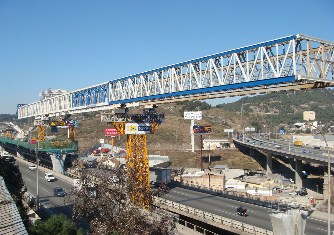
Mounting the structural elements forming the deck was performed by using a conventional launching gantry initially designed for the assembly of decks using prefabricated concrete girders. It had to be appropriately adapted for use on this site.
One of the modifications consisted of reinforcing the structure of the launch girders to support the stress produced from their own weight during the auto-launching manoeuvre of the longest span (53.50m), with the cantilevered front end (Fig. 18), the size of which is greater than what is normally achieved in decks made from prefabricated concrete girders.
3.2.2Auxiliary structures
The launching girder is fitted with some square metal pieces, welded to the lower part which serves as track lanes as they rest on the upper wheels of the motorized metal trolleys. They can move in a longitudinal direction. The trolleys move along the girder-lane of latticework placed in a perpendicular direction for the lateral displacement of the whole unit.
There is a marked difference between the normal procedure for launching prefabricated concrete girders and the one used for placing metal latticework forming the decks of the Bus-HOV Viaduct. During the longitudinal displacement manoeuvre, the concrete girders are suspended from the bridge crane and moved along the intermediate space between the two huge girders in latticework of the launching gantry, without there being any interference as they move above the girders-lanes arranged for the lateral displacement of the unit.
Given the large exterior size of the transverse section of the latticework pieces (6.00m wide and 4.00m deep) and in addition bearing in mind the existing curvature of some of them, the space between the two girders is insufficient and therefore it is impossible to manoeuvre the longitudinal displacement into a similar position to that of the prefabricated concrete girders. The latticework suspended from the bridge crane must necessarily be placed at a lower level during the longitudinal displacement manoeuvre and pass below the girder-lane in the area where the deck has already been built.
A portico-shaped structure was mounted to provide support for the girder-lane at the adequate height. Its lintel was formed by the girder-lane itself. (Fig. 19). The portico was closed at the lower part using a jamb connection piece in order to transmit vertical loads to intermediate points located on the axes of the semicircular profiles forming the upper chord of the latticework of the constructed deck. Horizontal arms stem in a perpendicular direction from the lower jamb connection piece. They are anchored at the end to the deck slab and used to provide stability to the whole structure.

The girder-lane is mounted on a metal structure that rests eccentrically on a limited space of the upper head on each pier in the front part of the area where each deck in being built. This is in order to leave free space for supporting the deck latticework pending placement (Fig. 20).

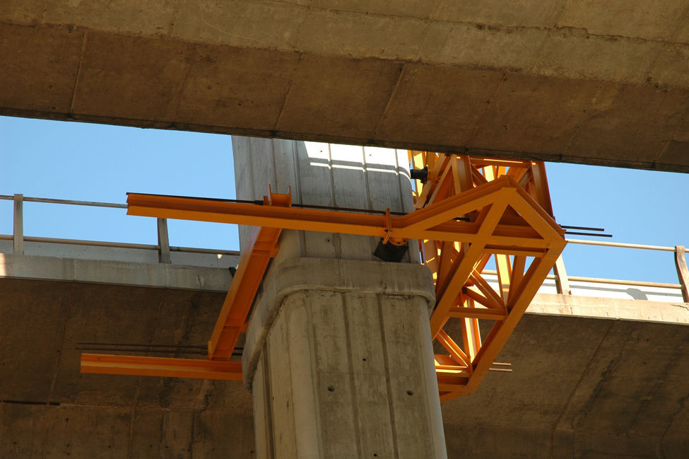
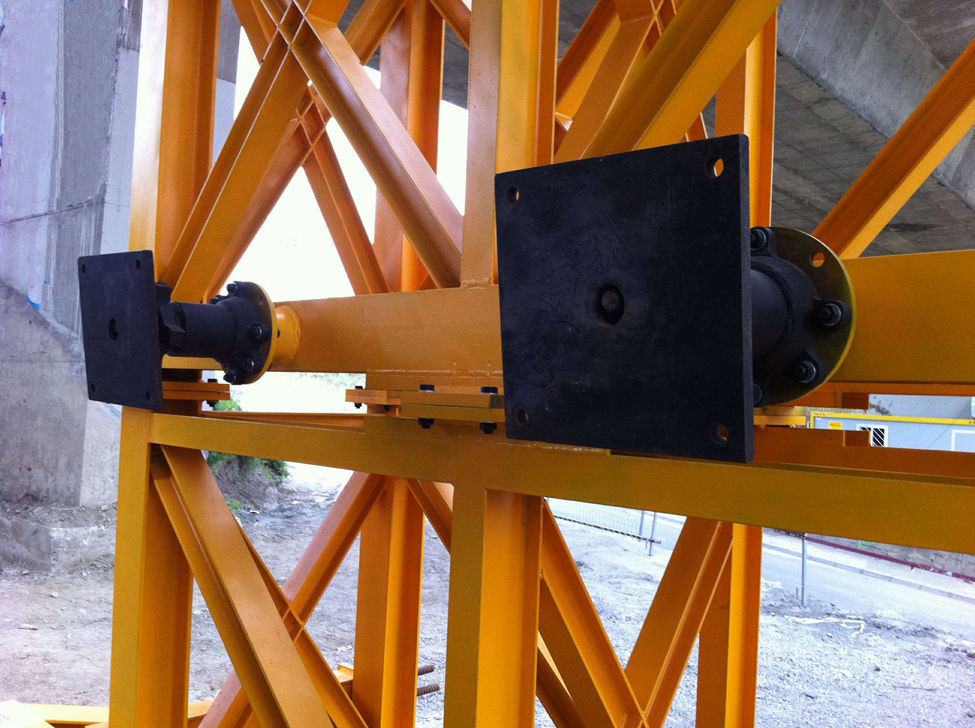
The front auxiliary structure is rigidly joined to the concrete pier using an adjustable fastening system (Fig. 21), equipped with prestressed bars. There is no need to create any voids to support them or any additional holes, the existence of which alter the appearance and aesthetics. Contact between the metal structure and the concrete pier is achieved through some bumpers fitted with spherical hinges and a regulation screw spindle (Fig. 22).


In order to proceed with the assembly, each metal structure was put into position on the pier by crane. Contact of all the bumpers was ensured to the concrete pier by tightening the screws. The bars were then tensed so that the structure remained perfectly solid with the pier without any clearance and ready to provide the appropriate support for the launching gantry used for the deck assembly. The tensile force of the bars was determined so that at no time during the construction stages, when the structure was operative, any detachment could take place between the bumpers and the concrete surface of the pier.
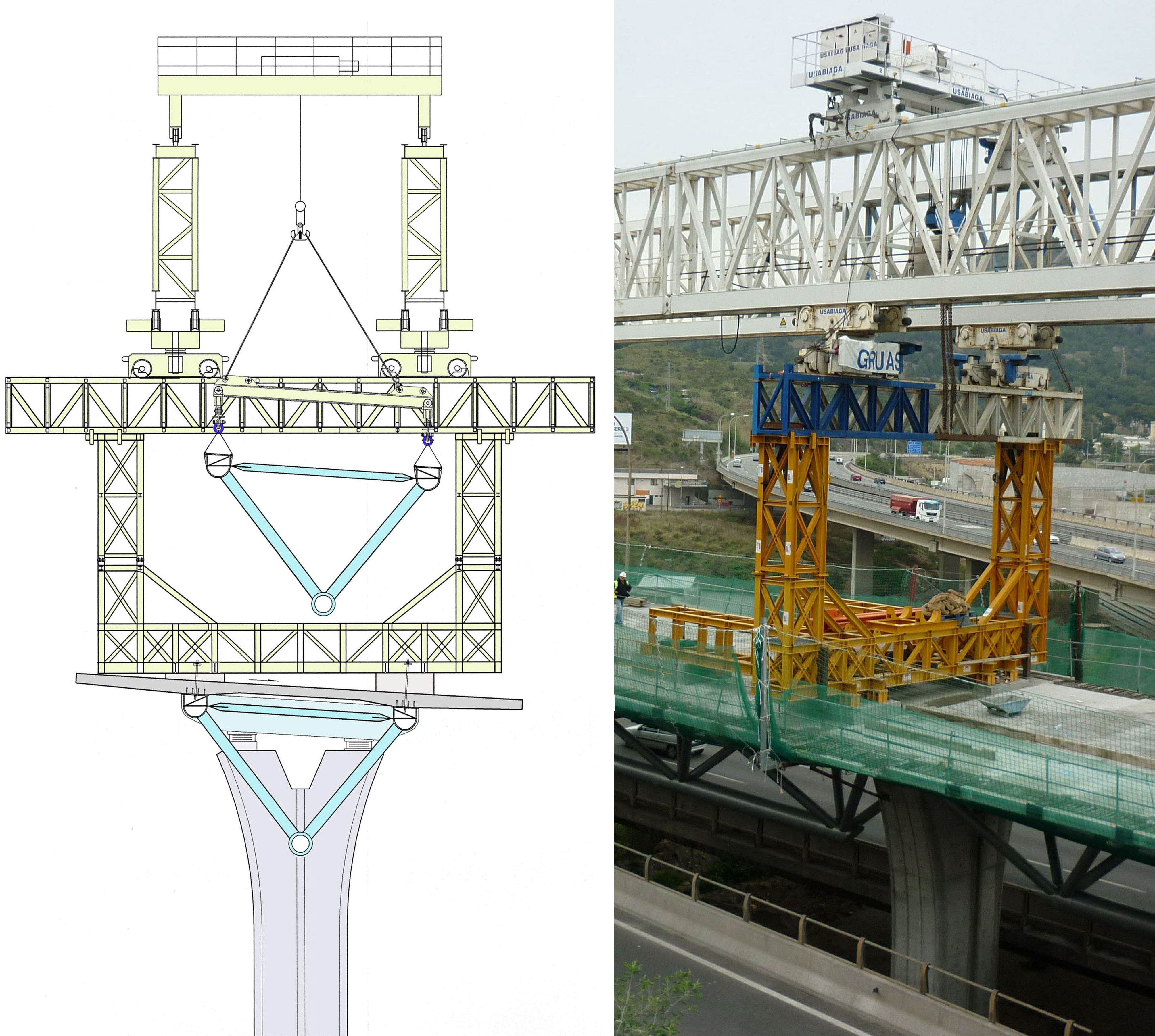
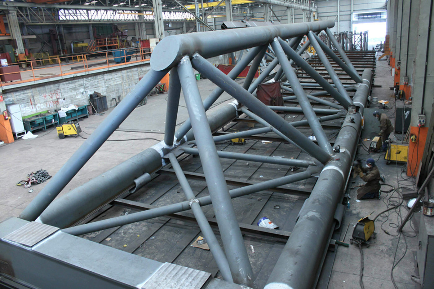
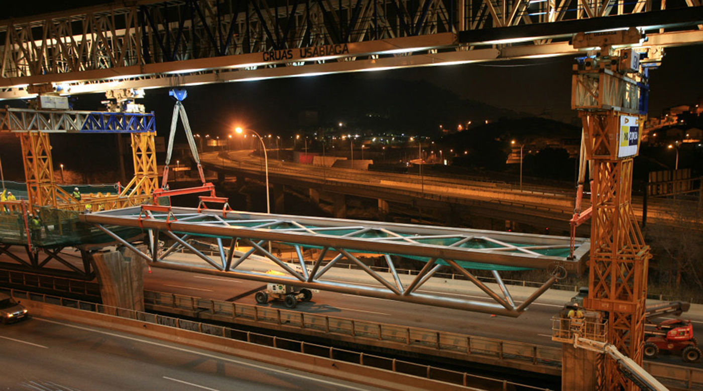
3.2.3Mounting the deckThe spatial tubular structure of each deck was built entirely in a workshop in an inverted position (Fig. 23).

After undertaking the geometric control and weld monitoring operations, the structure was inverted and transported to the site for placement in its final position.
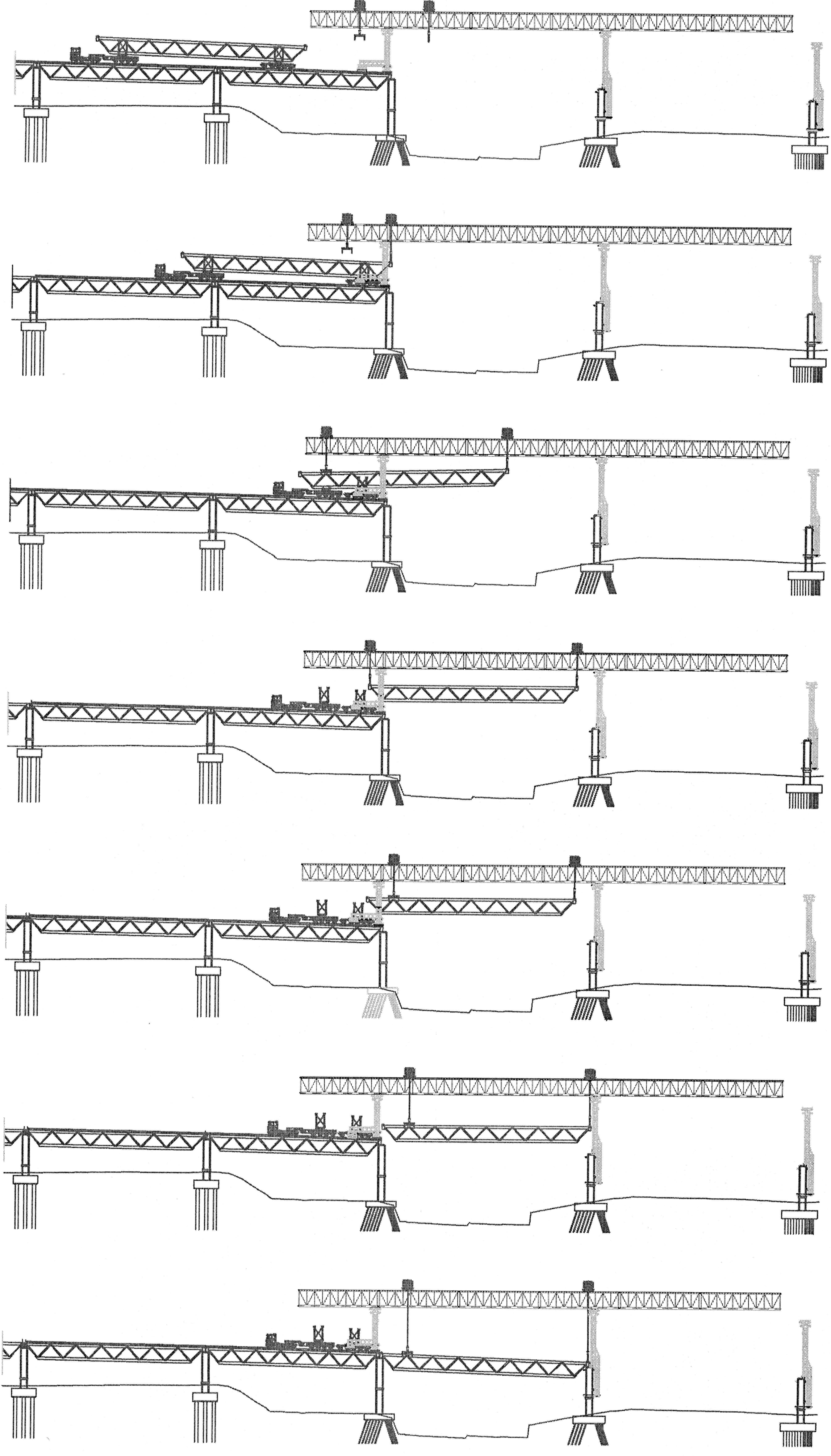
Fig. 24 represents the stages for placing a lattice girder once it arrived at the building site. The manoeuvres are indicated schematically during the longitudinal displacement of the latticework en route along the support of the launching gantry where it was necessary to change its rear hanging position, due to the fact that the latticework was placed below the girder-lane, blocking the passage of the hanging elements when suspended.

All the operations for mounting the deck were carried out overnight and the motorway traffic was maintained at all times, although only the outer lanes of the deck were used for the passage of vehicles, leaving the others available for use by staff and auxiliary site elements (Fig. 25).

Once the manoeuvres for placing the latticework concluded, the launching gantry itself was mounted onto the upper platform of the deck, formed by prefabricated slabs (Fig. 26) fitted with recesses for connection to the metal structure.
4Conclusions
Choosing the special configuration of the BUS-HOV lane Viaduct of Barcelona was motivated by the need to extend the C-58 Motorway, together with the limited space available. The newly built viaduct has not required any complementary occupation of the existing motorway.
The project undertaken has the special feature of singularity due to its location, with piers that rise out of the intermediate space of the decks of the existing viaduct. The deck shapes, formed by the spatial structure, respond to the aesthetic requirements and to their integration with the environment. An innovative building system was designed, so that vehicle traffic was maintained throughout the time the project was built. Finally, it is worth noting that the project was carried out very quickly, due to the advantage that practically the whole deck was built on the ground and then assembled using special elements.
5ExecutionProperty owners: TABASA.
Project and technical assistance given to the contractors: EIPSA.
Contractors [Temporary Consortium]: U.T.E. OHL – COPCISA.
Inauguration: October 2012.