

This paper investigates the use of concrete containing ultra-rapid hardening cement for rapid repairs in confined spaces where the repaired element has to sustain dynamic loading within a short time after repair. The study focuses on the early-age strength development and structural integrity of the repaired element. The study is divided in two parts. The first part is devoted to the compressive and split cylinder strengths, and to the temperature rise under adiabatic conditions in the concrete repair material from early-age (1h after casting) to 7 days of age. The second part of the study focuses on the finite element thermal and thermo-mechanical analysis of three repair options of a damaged concrete element in a confined space using simplified pseudo-static loading characteristics for the repaired element.
En este artículo se analiza la utilización de un hormigón fabricado mediante cemento de endurecimiento ultra-rápido para la reparación urgente en espacios confinados, donde los elementos reparados son sometidos a cargas dinámicas poco tiempo después de su reparación. La investigación se centra principalmente en el estudio del desarrollo de la resistencia del material a edades tempranas, así como de la integridad estructural del elemento reparado. El trabajo se ha dividido en 2 partes. En la primera parte se analiza la resistencia a compresión, la resistencia a tracción indirecta y el aumento de temperatura bajo condiciones adiabáticas del hormigón de reparación desde una edad muy temprana (1h después del hormigonado) hasta una edad de 7 días. En la segunda parte de la investigación se realiza un análisis térmico y termo-mecánico mediante elementos finitos de 3 opciones de reparación de un elemento de hormigón dañado y confinado en un espacio, utilizando cargas seudoestáticas simplificadas para el estudio del elemento reparado.
In some structural applications, the curing time of concrete must be reduced since there is an imperative need, in terms of reducing operational costs, of accelerating the strength gain of the material. In such applications, the utilisation of standard Portland cement is not convenient and the rapid hardening cements (also called ultra-high early strength cement) must be used in the concrete. Rapid-hardening hydraulic cement based concrete mix can attain the 28-day strength of an equivalent Portland cement mix [1] in less than six hours. Usually, this type of cement has high alumina and calcium sulfate content and a minor amount of reactive lime than Portland cements [2,3].
Rapid-hardening hydraulic cement has a chemical reaction different from Portland cement [3]. The reaction product is composed primarily of hydraulic tetracalcium trialuminate sulphate (CSA) and dicalcium silicate (C2S). Hydration of CSA leads to ettringite, which is a strong needle-like crystal that develops rapidly and gives the hydraulic cement a rapid hardening at early age [4]. It achieves strength much faster than Portland cement and many installations can be put into service in as little time as one hour. Another important aspect of this kind of cement is the absence of tricalcium aluminate (C3A), which provides a high durability of this material in sulfate environments [5].
Rapid-hardening hydraulic cement has been used for both concrete repair [6,7] and new construction [8], especially in concrete pavements [9], i.e. wherever superior durability and rapid strength gain are required. One relevant application where this kind of rapid hardening cement composite is very appropriate is as filling materials for 3-D concrete printers [10], where the setting of concrete must be precisely controlled.
In this paper, we investigate the use of a commercial concrete mix containing ultra-rapid hardening cement for rapid repairs in confined spaces where the repaired element has to be put into service within a short time after repair. The investigation focuses on the early age strength development and structural integrity of the repaired element. The investigation is divided in two parts. The first part is devoted to the determination of the compressive and split cylinder strengths, and to the temperature rise under adiabatic conditions in the commercial concrete repair material from early age (1h after casting) to 7 days of age. The second part of the investigation focuses on the finite element thermal and thermo-mechanical analysis of three repair options of a damaged concrete element in a confined space using simplified pseudo-static loading characteristic for the element application. The first part of the investigation which is a kind of forensic investigation was made necessary because the supplier of the ready-mix concrete repair material was reluctant for commercial reasons to reveal any information on the proportions of cement blend used in the ready-mix concrete material. From the results of the two investigations, it was possible to identify the origin of premature cracking in the repaired element and to suggest a solution to avoid this problem.
2Theoretical background. Heat of hydration of cement based materialsSince the early age behaviour of the rapid hardening cement is crucial and as no information about the cement blend in the concrete mix was supplied, a thermo-mechanical model for the analysis of the heat of hydration of the different cement blends and solutions had to be used as a forensic tool. The model used to predict the evolution of the heat of hydration is that proposed by Schindler and Folliard [11] (see also [12]).
The model of Schindler and Folliard considers the heat of hydration flux of the cement transferred to the concrete mix. According to this model, the total heat of hydration of a Portland cement class is a function of that provided by its components:
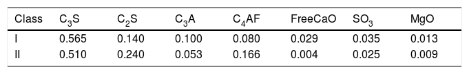
where Hcem is the total heat of hydration of the Portland cement (J/g) considering fully-hydrated cement and pi is the ratio of the mass of the ith component to the total cement mass. Table 1 shows the components of cement classes I and II [13].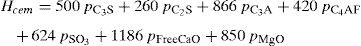
The evolution of the hydration of the Portland cement can be evaluated by means of the degree of hydration, δ, which varies from 0 to 1 (1 means complete hydration). This variable is stated as the ratio of the heat of hydration generated at a given time t, H(t) in J/g, to the total heat produced in the reaction [14]:

Hu is the total heat available for the hydration reaction, Hu=Hcem.
The degree of hydration is usually considered as an exponential function as follows:
where δu is the total degree of hydration, β the hydration shape parameter, τ the hydration time parameter (in hours), and te the equivalent age (in hours) at the reference temperature, Tr (K), which is given by: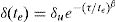
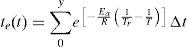
Here, Δt is the time interval (in hours), T is the average temperature of the concrete mix (in K), R is the universal gas constant (8.314J/mol/K), and Ea is the activation energy (J/mol) defined as proposed in [11] which is in accordance to the Arrhenius theory considered in the maturity method [15].
When all the parameters are known, the rate of the heat generation due to the hydration process of the cement, Qh, can be obtained as:
with Wc being the cement content (kg/m3). A more detailed description of the model can be found in [11,14].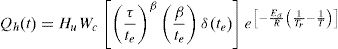
The heat equation, which can be solved by means of numerical methods (e.g. FEM), is then used to determine the evolution of the temperature in the concrete mix at any instant t by:
where ρ is the density, cp is the specific heat, k is the thermal conductivity, and the source term is the volumetric heat flux as defined in Eq. (5).
Eq. (6) can be solved by FEM (e.g. LUSAS software) to obtain the temperature evolution of the concrete mix at any point of the domain and at any instant during the hydration process of the cement. The thermo-mechanical model must consider this temperature field to evaluate the mechanical properties and determine the thermal stresses potentially inducing early age cracking of concrete. Convective and radiative boundary conditions must also be considered in the model through their corresponding heat fluxes, qcv and qrd, respectively:
h is the film coefficient between concrete and air, Tcv is the temperature of the convective boundary, Tr is the room temperature, σ is the Stefan-Boltzmann constant, ∈ is the emissivity, and Trd is the temperature of the radiative boundary.3Experimental programme3.1Concrete mix
The concrete repair material was supplied in bags ready for mixing with water. The concrete mix proportions were provided but without any information on the commercially sensitive cement blend proportions apart from an indication that the blend contained a rapid hardening cement and standard Portland cement class I. To produce the concrete, we just had to add water to the dry ingredients (2.25kg of water for each 25kg bag of mix) and mix them in a normal mixer following the mixing instructions described on the bags and the data sheets. Our first investigation therefore was aimed firstly at checking whether the compressive and split cylinder strengths stated in the supplier data sheets could be reached, and secondly to get an idea of the proportions of rapid hardening cement and Portland cement class I in the blend by performing an adiabatic test. Henceforth, the commercial concrete repair material will be simply referred to as RHC.
3.2Compressive and split cylinder testsStandard cube (100mm) and cylinder (100mm diameter, 200mm height) specimens were cast from RHC. The specimens were tested according to British Standard procedures [16–18] at various ages after casting: 60min, 90min, 7h, 24h, and 7 days. The specimens tested at 60 and 90min ages were only air cured, whereas those at later ages were water cured.
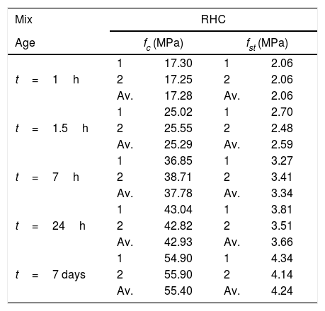
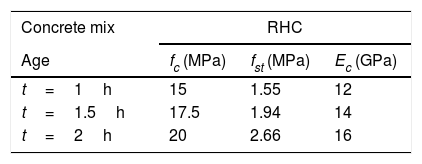
The mix was very wet after mixing, but it hardened within minutes in the mould. The results of compressive (fc) and split cylinder (fst) tests are given in Table 2. The compressive strength at all ages is consistently higher than the characteristic value stated in the product data sheets (Table 3).
Evolution of strength of RHC mix with age.
| Mix | RHC | |||
|---|---|---|---|---|
| Age | fc (MPa) | fst (MPa) | ||
| t=1h | 1 | 17.30 | 1 | 2.06 |
| 2 | 17.25 | 2 | 2.06 | |
| Av. | 17.28 | Av. | 2.06 | |
| t=1.5h | 1 | 25.02 | 1 | 2.70 |
| 2 | 25.55 | 2 | 2.48 | |
| Av. | 25.29 | Av. | 2.59 | |
| t=7h | 1 | 36.85 | 1 | 3.27 |
| 2 | 38.71 | 2 | 3.41 | |
| Av. | 37.78 | Av. | 3.34 | |
| t=24h | 1 | 43.04 | 1 | 3.81 |
| 2 | 42.82 | 2 | 3.51 | |
| Av. | 42.93 | Av. | 3.66 | |
| t=7 days | 1 | 54.90 | 1 | 4.34 |
| 2 | 55.90 | 2 | 4.14 | |
| Av. | 55.40 | Av. | 4.24 | |
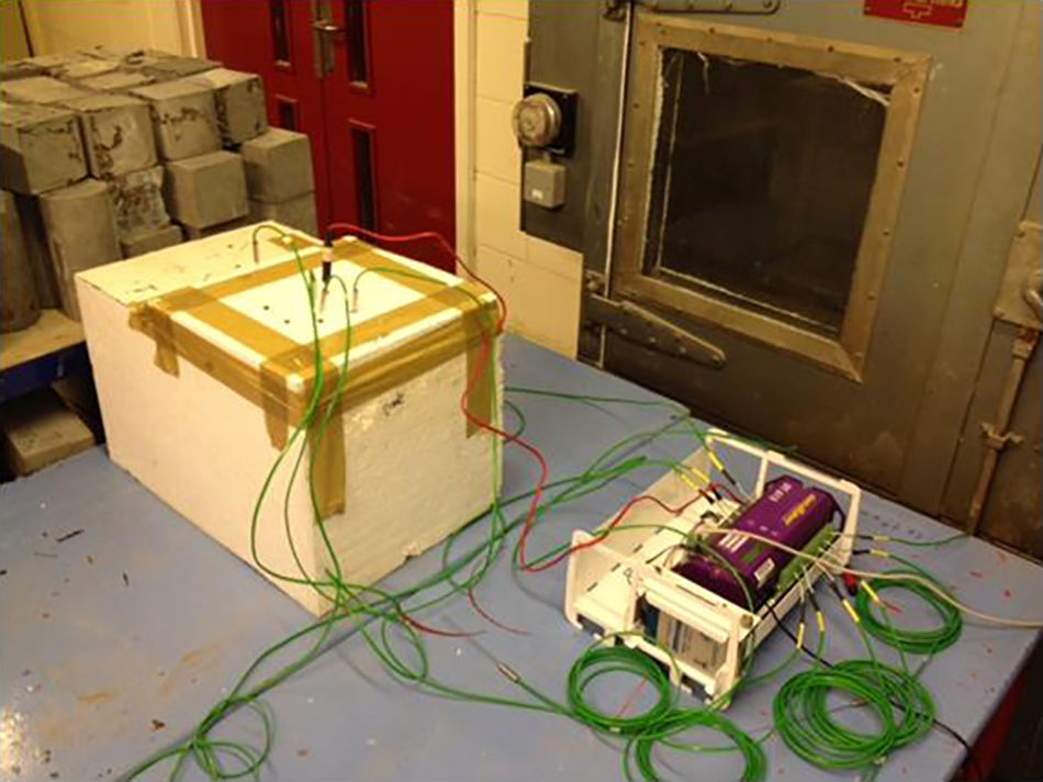
This test was performed using a large polystyrene block in which a cubical cavity (roughly 150mm side) had been made with a sharp blade. The sides of the cavity were lined with aluminium foil. The cavity was filled with the wet mix and covered first with aluminium foil and then a polystyrene lid. The lid was secured to the block with packaging tape. Five K-type thermocouples (up to 150mm shaft length) were inserted through the lid into the mix within less than 5min of mixing. A typical set up is shown in Fig. 1. The thermocouples were connected to a data logger set to record the temperature readings every minute until steady state conditions had been reached. This rudimentary test set up ensures nearly adiabatic conditions until steady state but not thereafter. A more detailed explanation of several methods for determining the temperature rise in concrete is given in [19] and a procedure for estimation of concrete adiabatic temperature rise by semi-adiabatic temperature rise tests is given in [20].

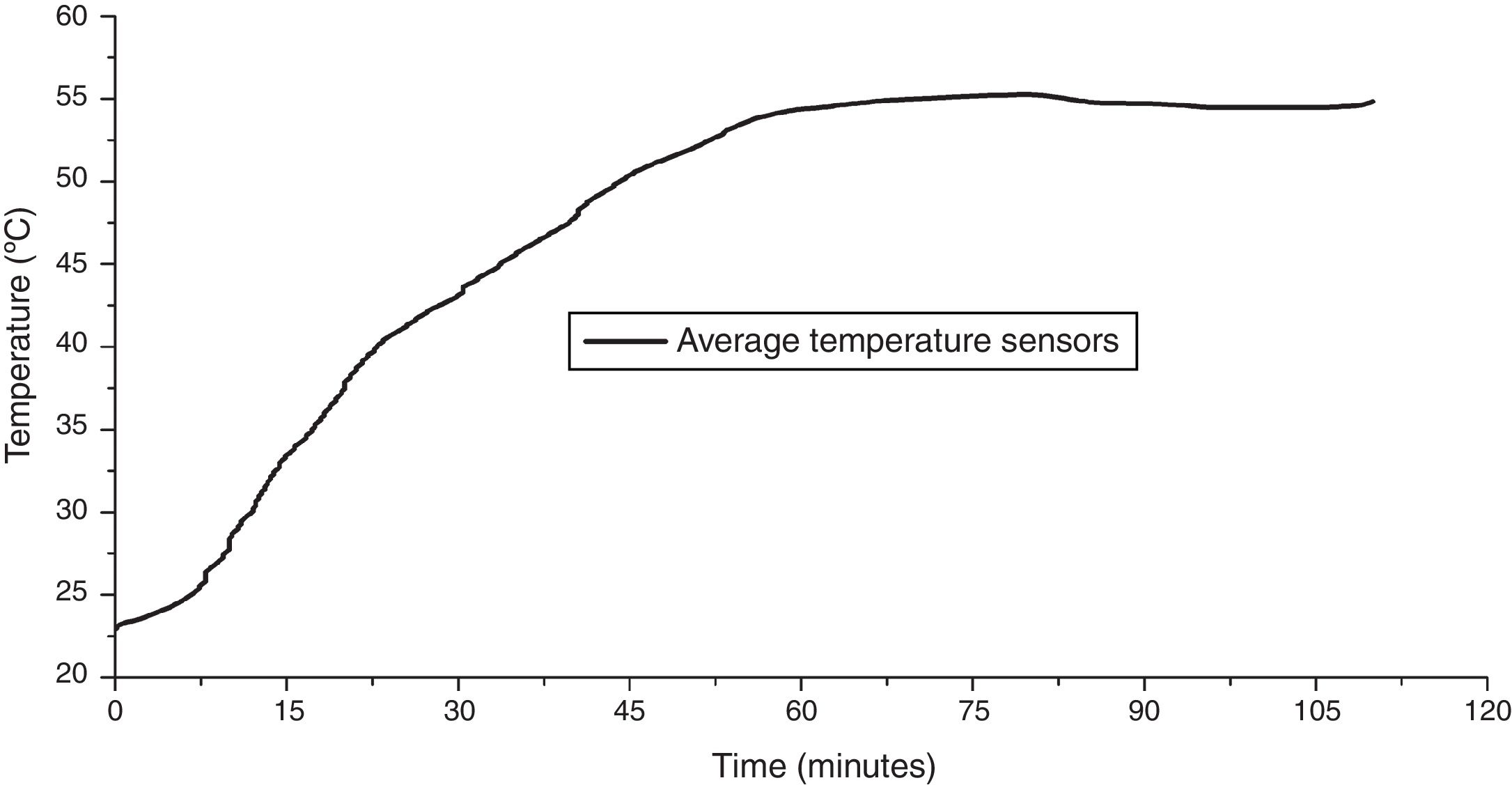
In our case, several tests with different materials were performed. Fig. 2 shows the response of the most representative RHC mix that we studied in detail. The maximum temperature rise was registered at about 55°C from an ambient temperature of 22°C in 85–95min after mixing. Note that there is practically no delay before the temperature of the mix began to rise.
3.4Simulation of hydration kinetics
The hydration kinetics of any binder containing Portland cement can be accurately simulated under fully insulated (adiabatic) conditions using available simulation tools (e.g. LUSAS), provided its chemical composition is known, according to the method of Schindler and Folliard previously described. As mentioned above the suppliers of the RHC mix were only willing to say that the binder is a blend of calcium sulpho-aluminate (CSA) cement and Cem I, but for commercial reasons were not prepared to reveal the proportions of these two components. We had therefore to undertake a forensic investigation in order to gain an understanding of what we had observed in the adiabatic test on RHC mix.
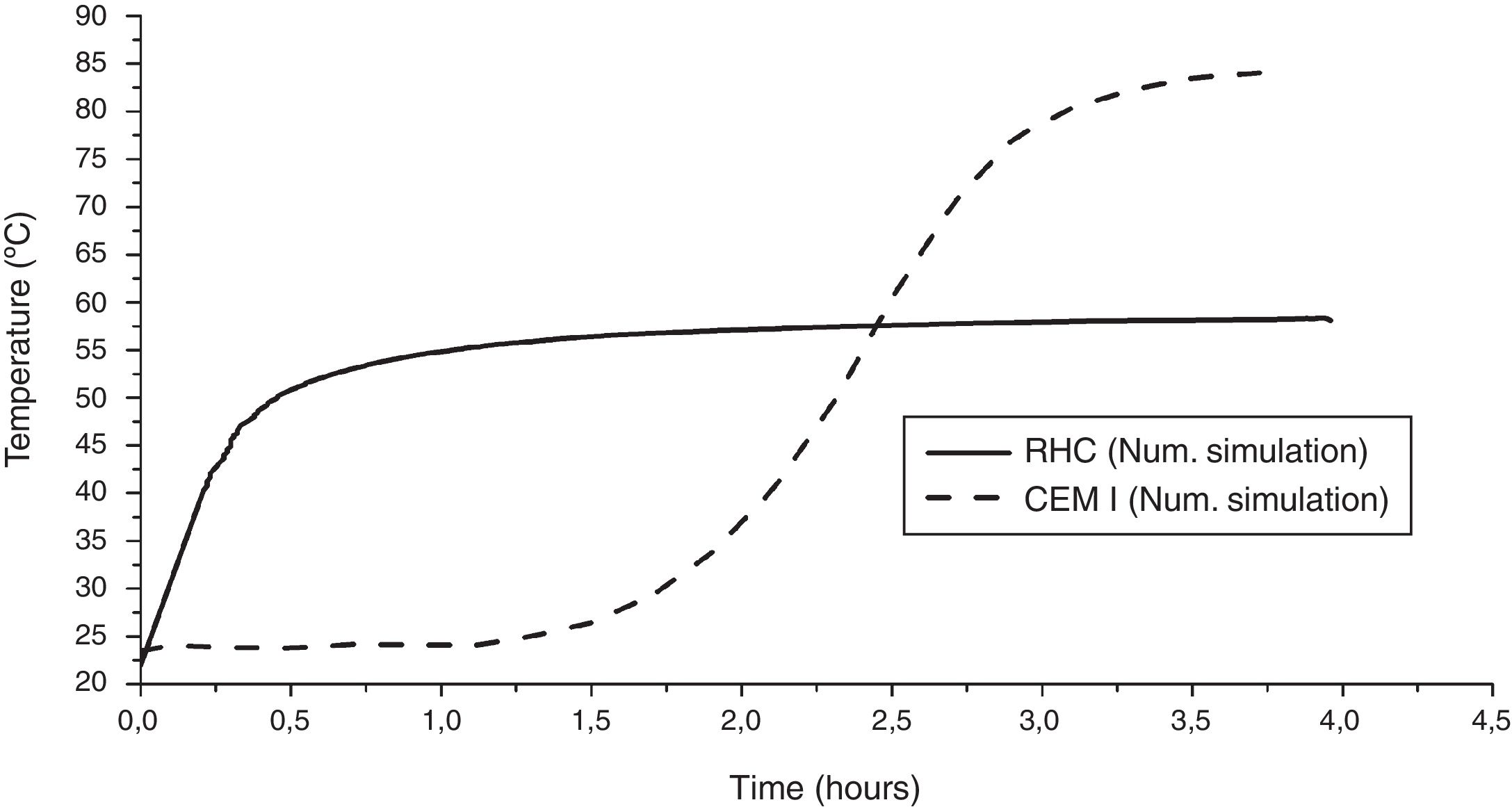
We first simulated the hydration kinetics of Cem I for which the chemical composition is well characterised. We assumed that the mix contained 450kg/m3 of Cem I only. As Cem I is blended with fly ash and therefore contains free lime, we expected it to reach a high temperature but after several hours of hydration following an equally substantial delay in the start of the hydration process. The simulations (Fig. 3) completely agree with the expected behaviour of Cem I. This gave us confidence in trying to reproduce the observed behaviour of the blended binder in the RHC mix (Fig. 2).
 and in RHC mix. The horizontal scale shows time in hours and the vertical scale temperature in °C.")
In the absence of information on the exact proportions of CSA and Cem I in the binder blend of RHC mix, we had to perform many trial simulations in order to reproduce as closely as possible the recorded temperature rise against time curve of RHC mix. The results are also shown in Fig. 3.
Fig. 3 compares favourably with the recorded response (Fig. 2) if the amount of Cem I in the CSA+Cem I blend available for hydration is 280kg/m3.
It would appear therefore that the CSA+Cem I blended binder in RHC mix contains 280kg/m3 of Cem I. As concrete with a 28-day characteristic compressive strength of 55MPa (the 28-day characteristic strength specified in the RHC product sheets) usually contains about 350–400kg/m3 of binder, it appears that the CSA content in RHC mix is between 70 and 120kg/m3 (i.e. the proportions of CSA and Cem I are in the range between 0.2:0.8 and 0.3:0.7).
4Thermal and thermo-mechanical analysisThe aim of the thermal (up to 90min) and the coupled thermo-mechanical analysis (from 91 to 120min) when the infill concrete is still hydrating while the load has come on the repaired element is to study the role of early age properties of RHC mix (summarised in Table 2) in the early age performance (up to 120min) of the three repair options. We have used the characteristic compressive strength values from the supplier's product data sheets (see Table 3) because the mean values we measured (see Table 2) exceed the characteristic values.
For modelling the multi-crack concrete model available in LUSAS was employed. This model considers the non-linear behaviour of concrete in compression, loss of tensile strength with compressive crushing, softening in tension leading to the formation of fully formed stress-free cracks, aggregate interlock on partially and fully formed cracks, and crack opening and closing with both shear and normal crack surface movements [21–23].
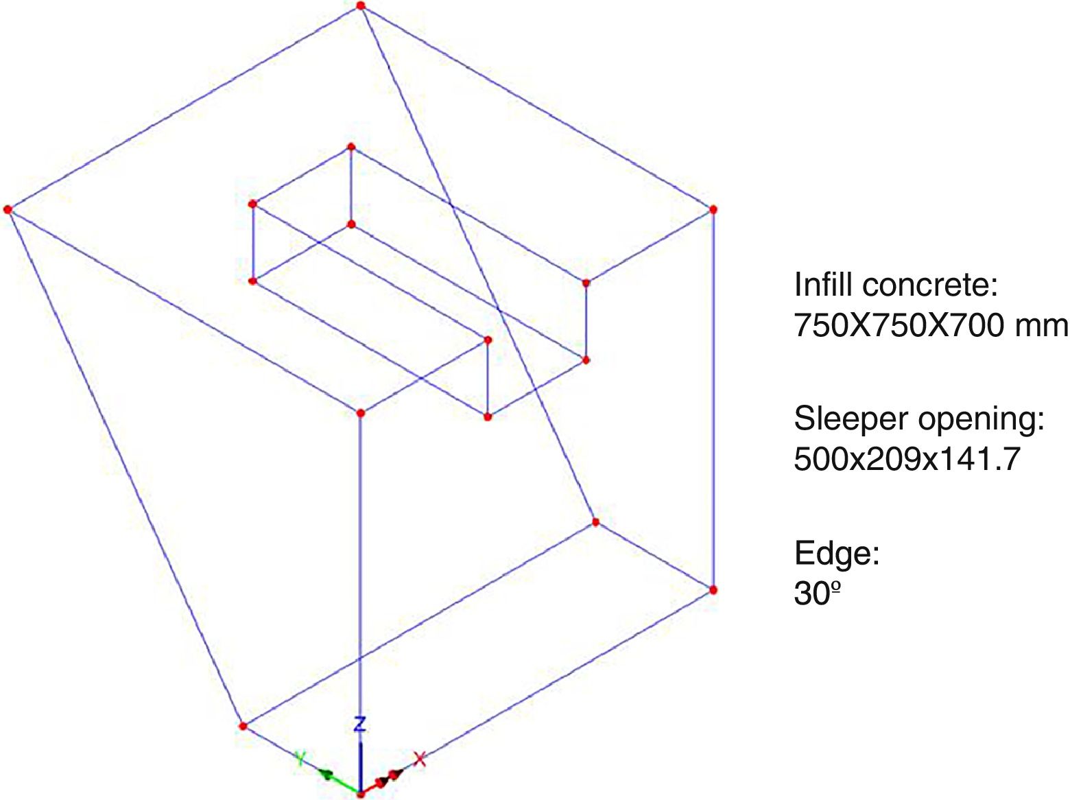
4.1Repair option 1In this repair option the old concrete sleeper and the surrounding concrete are removed to create a bed (black contour and grey shaded in Fig. 4) for “popping” in the new pre-stressed sleeper (red contour in Fig. 4) and grouting it to the existing concrete (blue contour in Fig. 4) with RHC. The dimensions of the bed and the infill grouting RHC are shown in Fig. 4 and the LUSAS finite element mesh (without the sleeper) in Fig. 5.


In the first 90min after the sleeper has been “popped” in and grouted with infill concrete RHC, the latter hydrates releasing heat. As the infill concrete is in frictional contact with the old concrete and the sleeper on the bottom and the sides are exposed to air on the top and at the front, some of the heat is dissipated by convection. The thermal analysis takes this into account through the use of appropriate convection coefficients between the fresh and old concrete and between the fresh concrete and air. The air temperature is assumed to be 27°C. The evolution of temperature with time in the RHC infill is shown in Fig. 6. The temperature profile in the infill concrete 90min after casting is shown in Fig. 7.

 has dropped below the peak value registered under adiabatic conditions (cf. Fig. 3).")
Temperature profile in RHC mix infill. Note that the maximum temperature at 90min (about 51°C) has dropped below the peak value registered under adiabatic conditions (cf. Fig. 3).
It is interesting to note that because of the confinement of infill concrete the temperature rise due to heat of hydration (Fig. 6) is only slightly lower than that registered under adiabatic conditions for RHC mix (cf. Fig. 3). Not surprisingly, the coolest regions, albeit still at well above the ambient temperature, are those that are exposed to air at the top and the front.
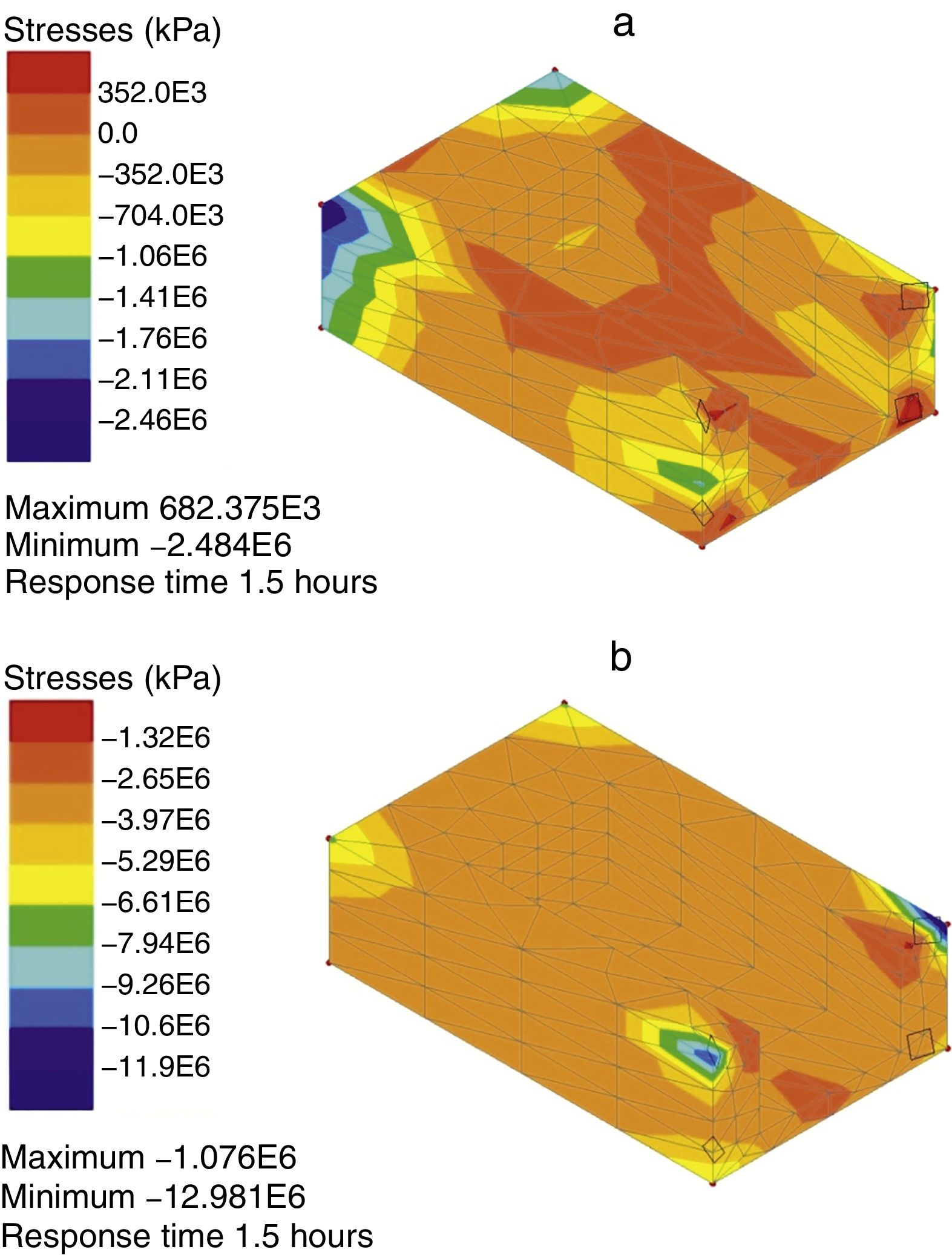
The contours of maximum and minimum principal thermal stresses (negative sign indicates compressive stress) in the infill RHC at age 90min are shown in Fig. 8.
 and minimum (b) principal thermal stresses in infill RHC mix at 90min age. The black diamonds indicate damage which is confined to corners.")
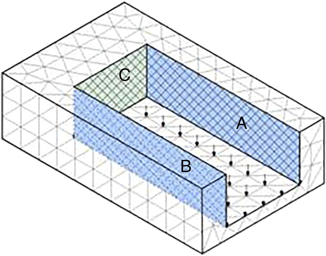
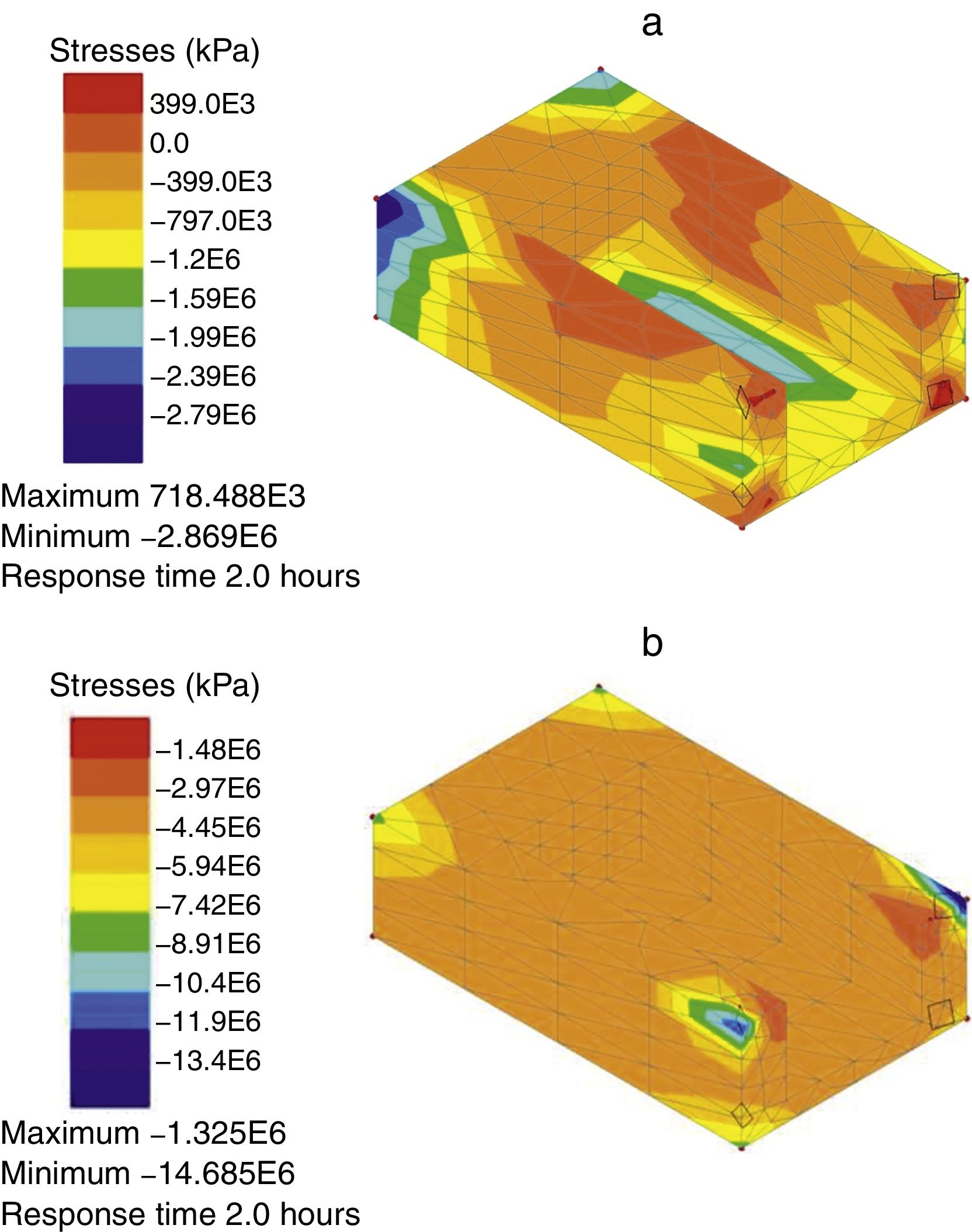
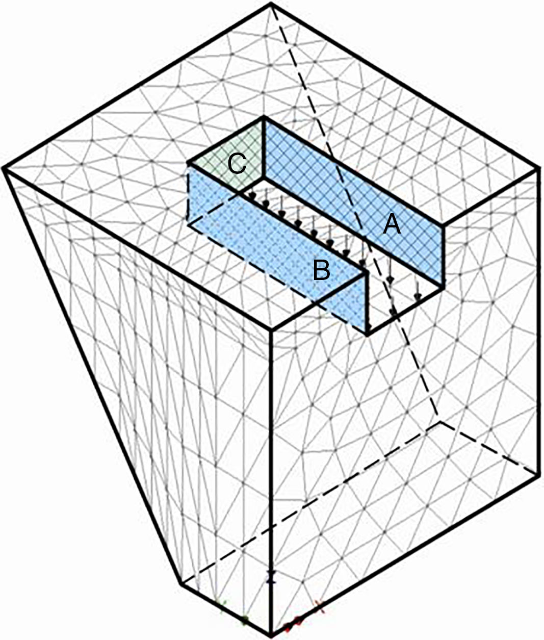
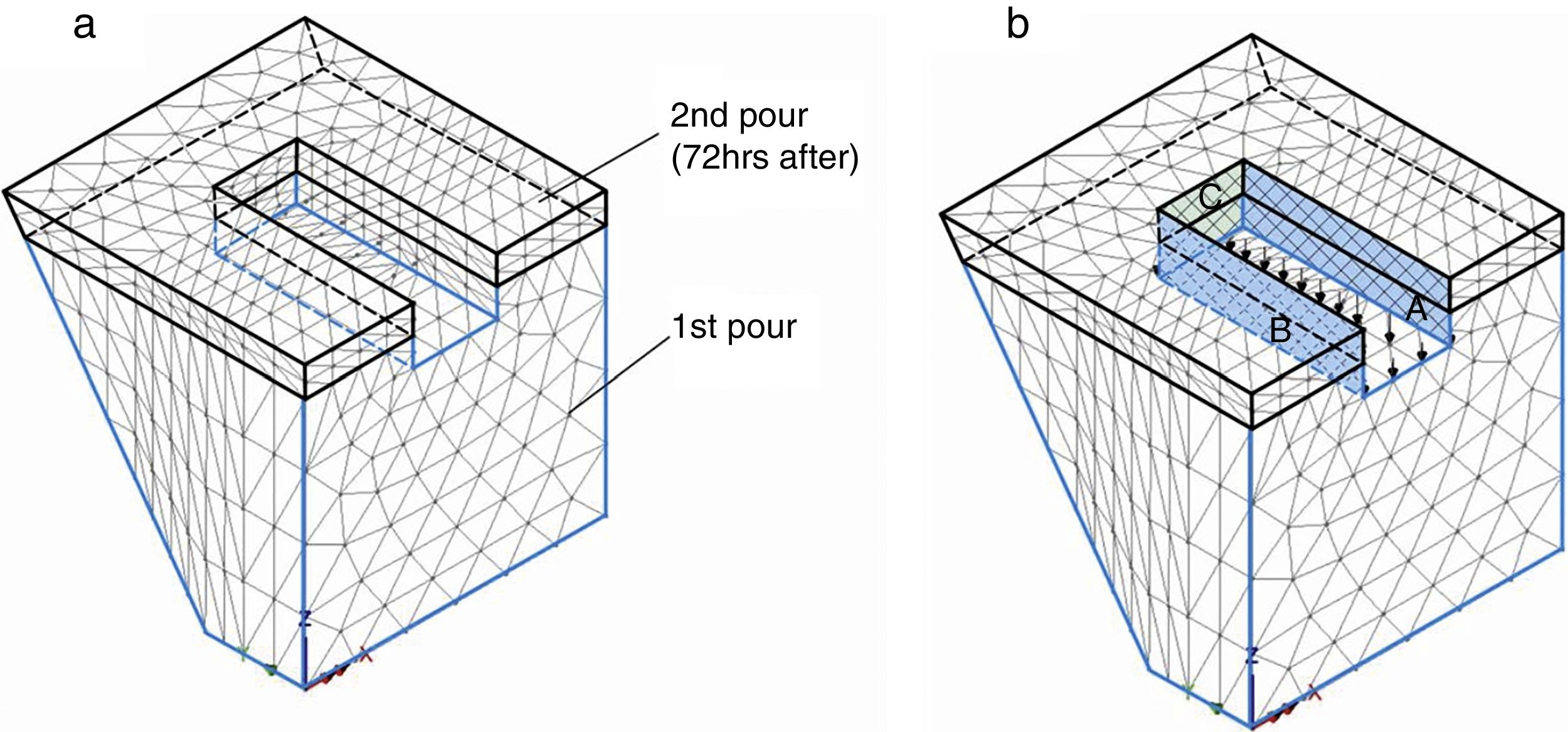
After 90min, the first axle traverses the sleeper applying a quasi-static equivalent load of 209kN to it. Assuming that the sleeper is in full contact with the bed of infill RHC, this concentrated load can be replaced by a uniform pressure on the bed applied in the negative z-direction, as shown in Fig. 9. At this stage we are considering only the most favourable load scenario which does not include any lateral loads in the x- and y-directions (Fig. 5). Moreover, as the hydration reaction in the infill RHC is still continuing, we perform a coupled thermo-inelastic analysis from 90 to 120min. In this coupled analysis, apart from the frictional contact (interface) between the old and infill concrete, we now allow a certain movement between the infill concrete and the sleeper. Thus, the surfaces A and B in Fig. 9 in contact with the sleeper are free to translate in the y-direction, whereas the surface C is free to translate in the x-direction. The contours of maximum and minimum principal thermo-mechanical stresses in the infill RHC at age 120min are shown in Fig. 10.

 and minimum (b) principal thermo-mechanical stress contours in the infill RHC at 120min age. Black diamonds which indicate areas of damage are confined to corners.")
As observed in Fig. 10, the minor damage generated is the same as at 90min age (Fig. 8). Thus the axle loading does not seem to have induced any additional damage.
4.2Observations on repair option 1Our coupled thermo-inelastic analysis of the hydrating infill RHC mix under vertical axle loading shows insignificant damage at 90min or 120min age. The minor damage apparent in Figs. 8 and 10 is because of the stress concentration at sharp corners. The situation may however change if lateral loads are also applied (see below).
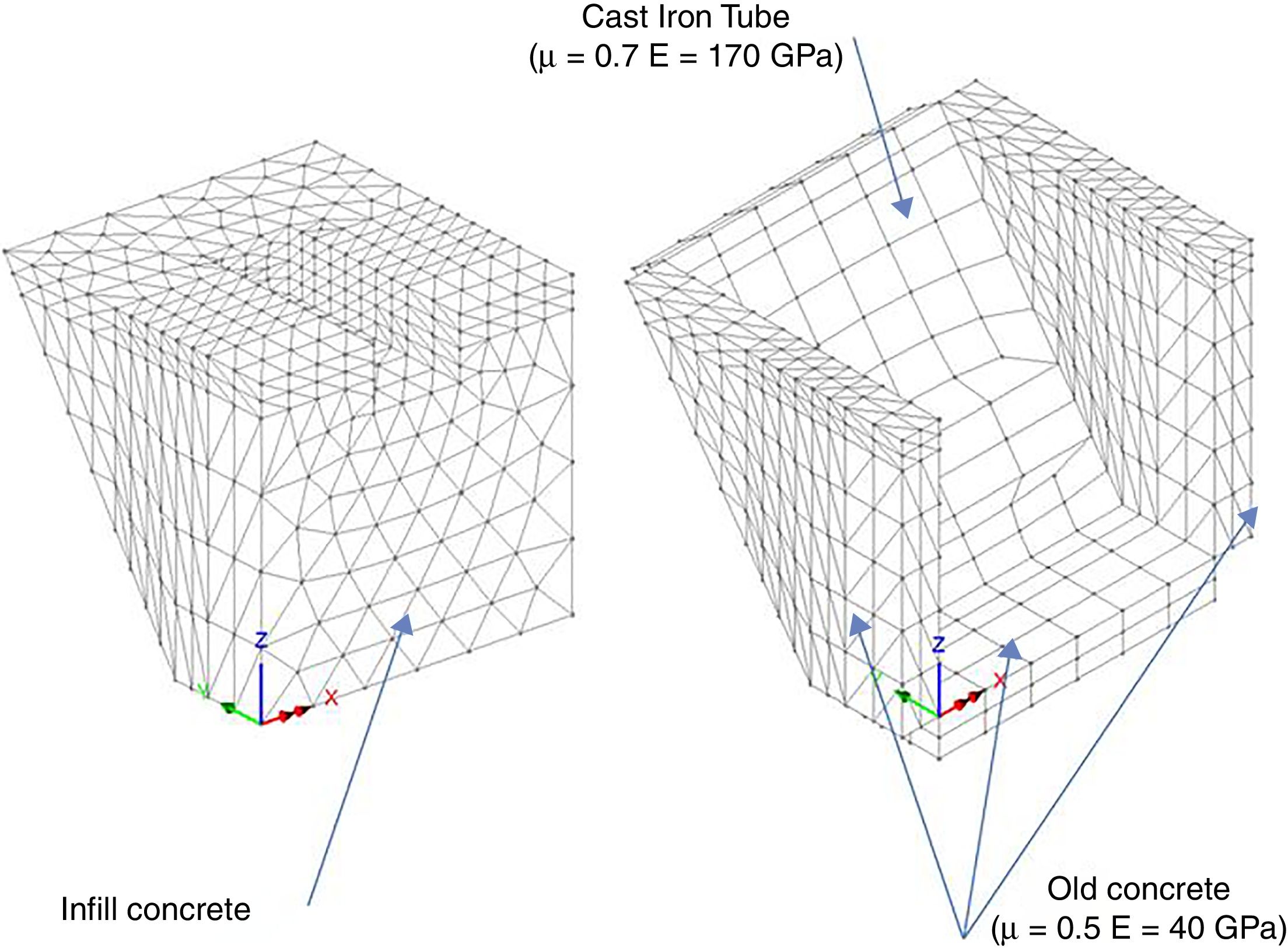
4.3Repair option 2In this repair option the old concrete sleeper and the entire concrete seat are removed to create a bed which is infilled in one continuous pour with RHC mix in readiness for a new pre-stressed sleeper (Fig. 11).

The thermal and thermo-inelastic analysis of the infill RHC concrete in the repair option 2 followed the same sequence as in the repair option 1 above. The evolution of temperature due to the heat of hydration was followed up to 90min age. Following that the vertical axle loading was applied to the sleeper and the thermo-inelastic analysis continued up to 120min age. Frictional contact was assumed between the old concrete and cast iron tunnel lining and the infill RHC concrete as shown in Fig. 12. The same boundary conditions between the infill RHC concrete and the sleeper (Fig. 13) were assumed as in the repair option 1.


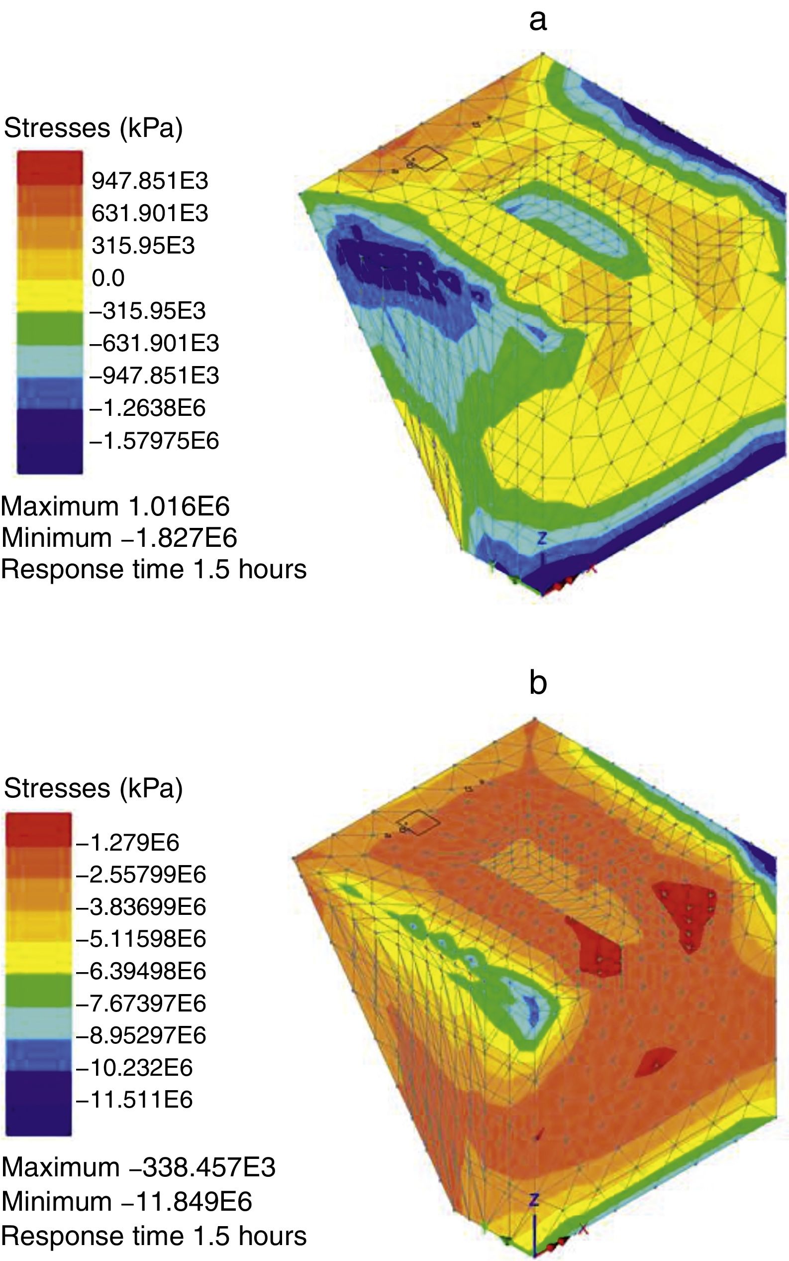
The principal thermal stresses at age 90min in the infill RHC concrete are shown in Fig. 14.
 and minimum (b) principal thermal stresses in RHC infill concrete at 90min age. There is some minor top surface damage (black diamonds).")
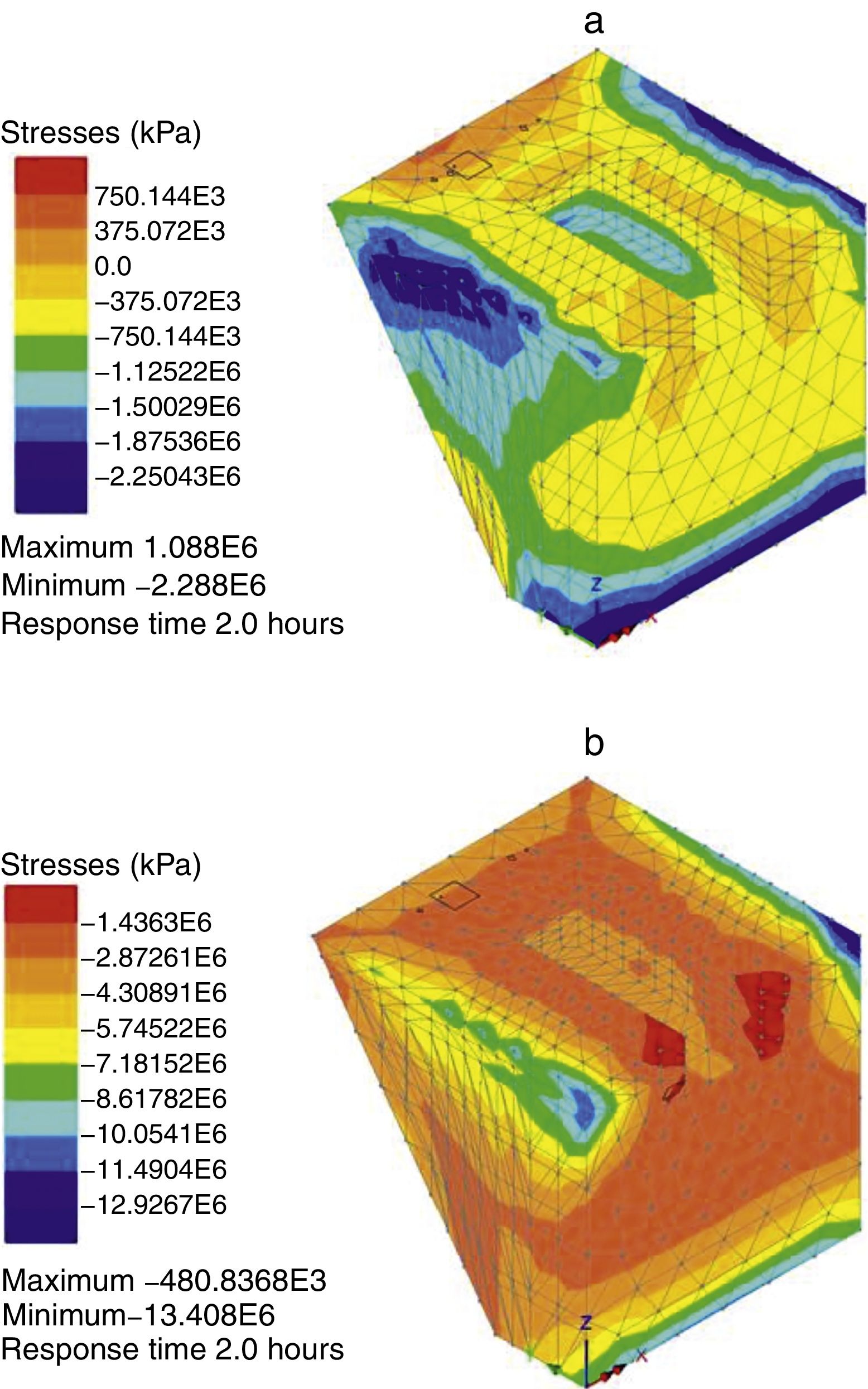
The principal thermo-mechanical stresses induced in the infill RHC concrete by both the temperature and the vertical axle loading at 120min age are shown in Fig. 15. A comparison with Fig. 14 shows that the vertical axle loading does not induce any damage additional to the minor thermal damage already present at 90min age.
 and minimum (b) principal thermo-mechanical stresses in RHC infill concrete at 120min age. Note that there is practically no change in the minor thermal damage from 90min age (cf. Fig. 14).")
Maximum (a) and minimum (b) principal thermo-mechanical stresses in RHC infill concrete at 120min age. Note that there is practically no change in the minor thermal damage from 90min age (cf. Fig. 14).
Our coupled thermo-inelastic analysis of the hydrating infill RHC concrete shows that the performance of RHC mix in the repair option 2 almost mirrors its performance in the repair option 1. It suffers very minor damage at both 90min and 120min age (Figs. 14 and 15). However, the situation is likely to change when lateral loads are also applied (see below).
4.5Repair option 3Repair option 3 is a modification of option 2 above. The infill RHC concrete block is cast in two pours, the first to level that just covers the sleeper re-bar and the second to final level with 3 days between pours. In this option, the wheel load is applied 90min after the second pour and there is an interface between the 3-days old first RHC pour and fresh second RHC pour. The geometry and the boundary conditions between the second pour and the sleeper are shown in Fig. 16.
 and loading scheme and contact conditions due to the train wheels (b).")
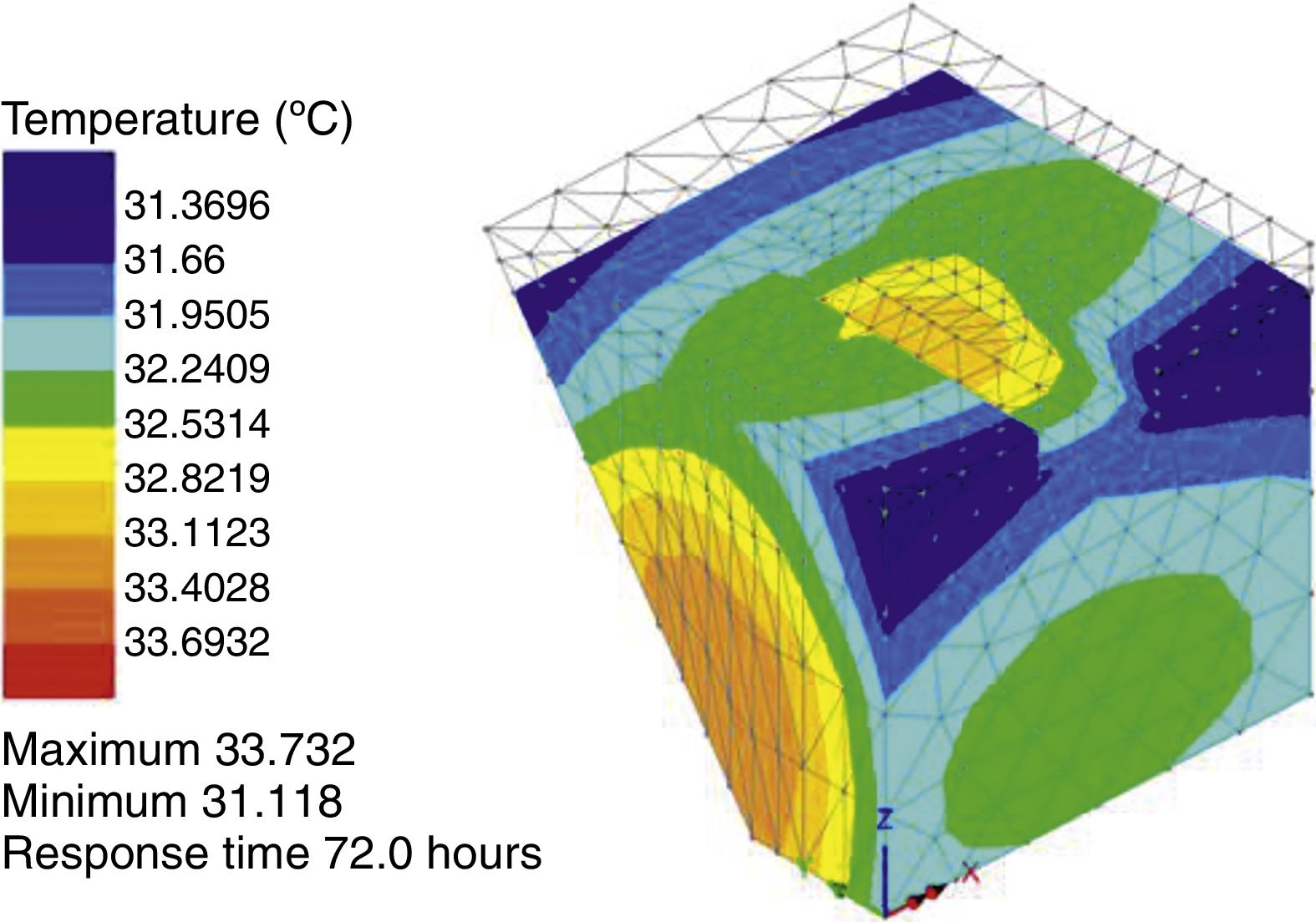
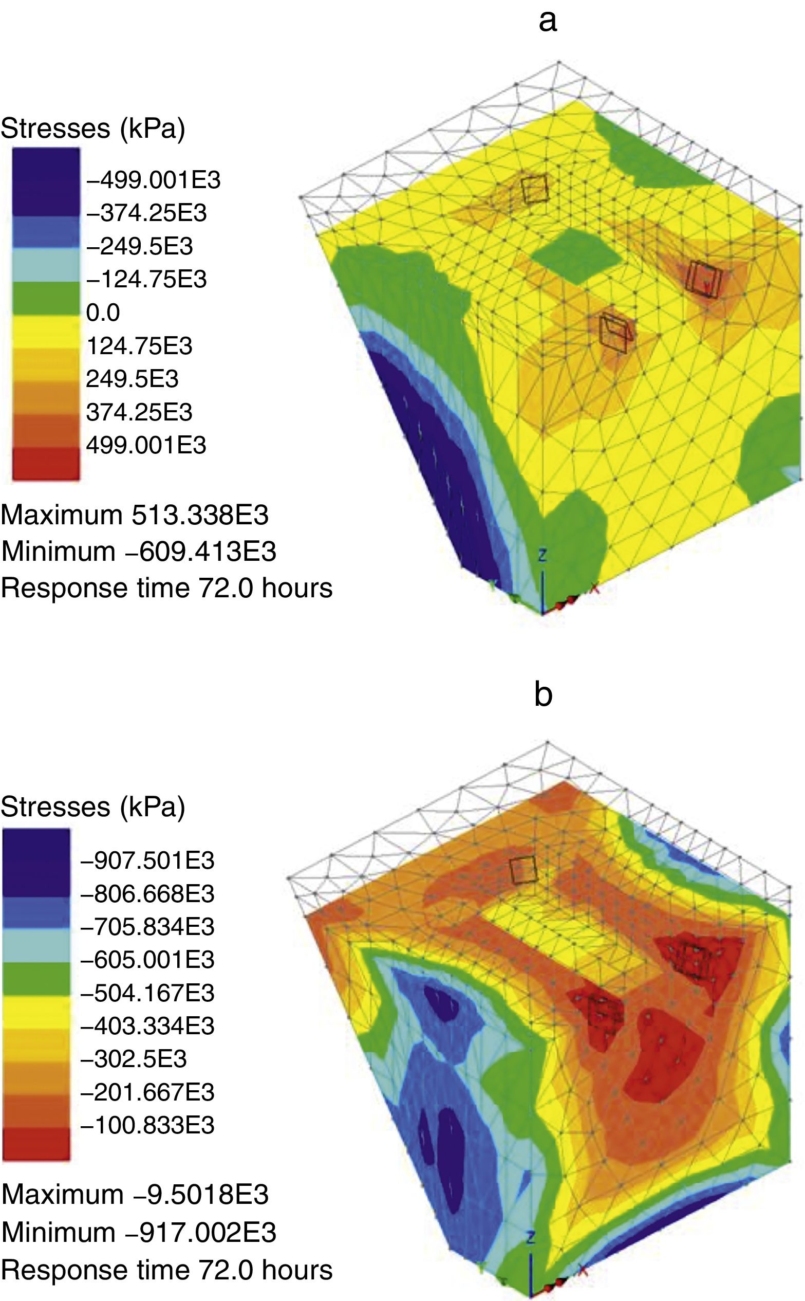
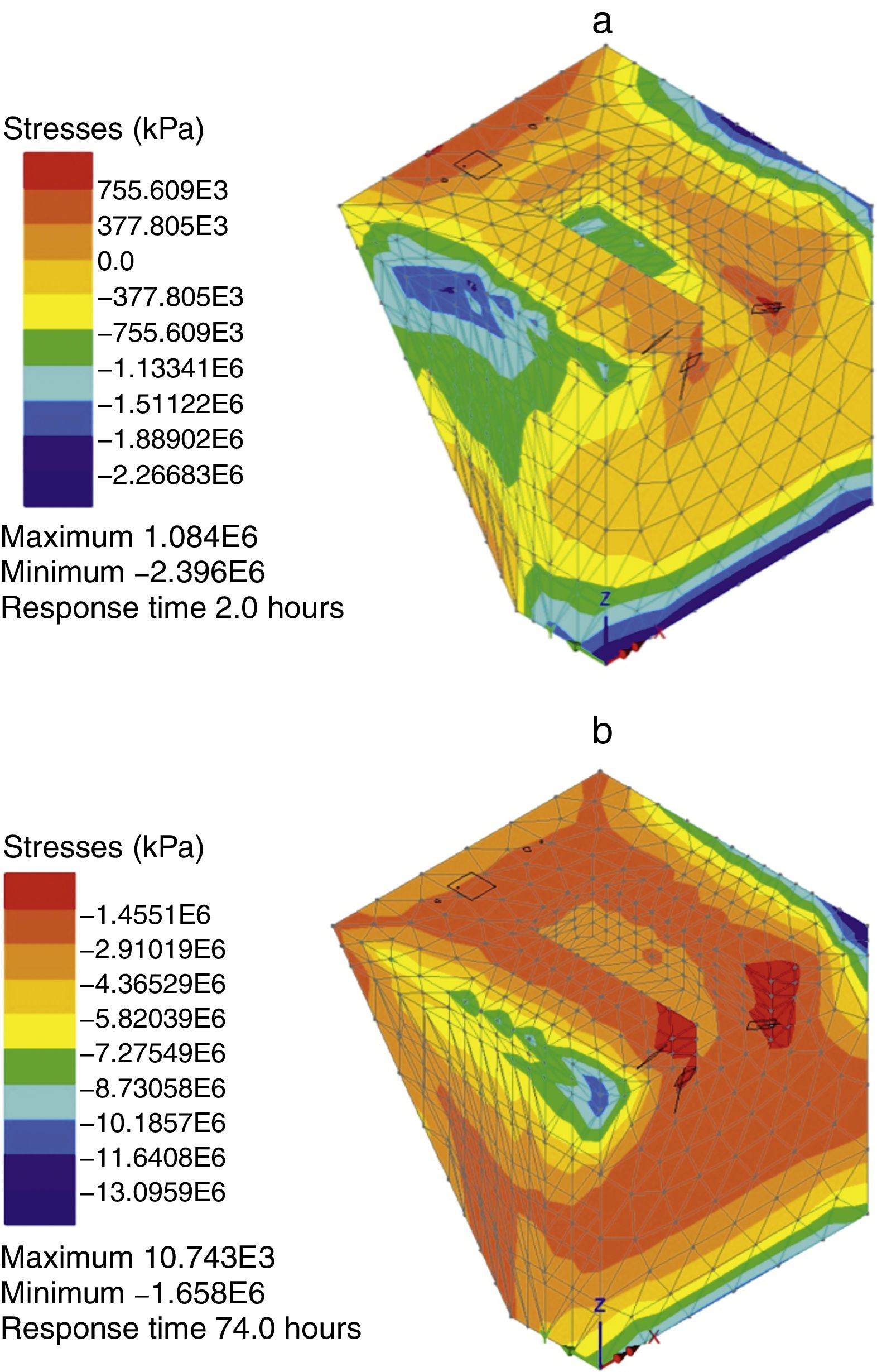
The thermal and thermo-mechanical analysis in this repair option mimics the casting steps. First, a thermal analysis of pour 1 is performed until 72h age. Next, the thermal analysis of this pour and pour 2 is performed for a further 90min. Finally, a thermo-mechanical analysis is performed until pour 2 reaches 120min age. The temperature profile in pour 1 at 72h age is shown in Fig. 17. Note that the maximum temperature has already reduced to less than 34°C. The corresponding thermal stresses at this age are shown in Fig. 18.

 and minimum (b) principal thermal stresses in infill RHC concrete pour 1 at 72h age. Note that there are a few thermal cracks in this infill concrete.")
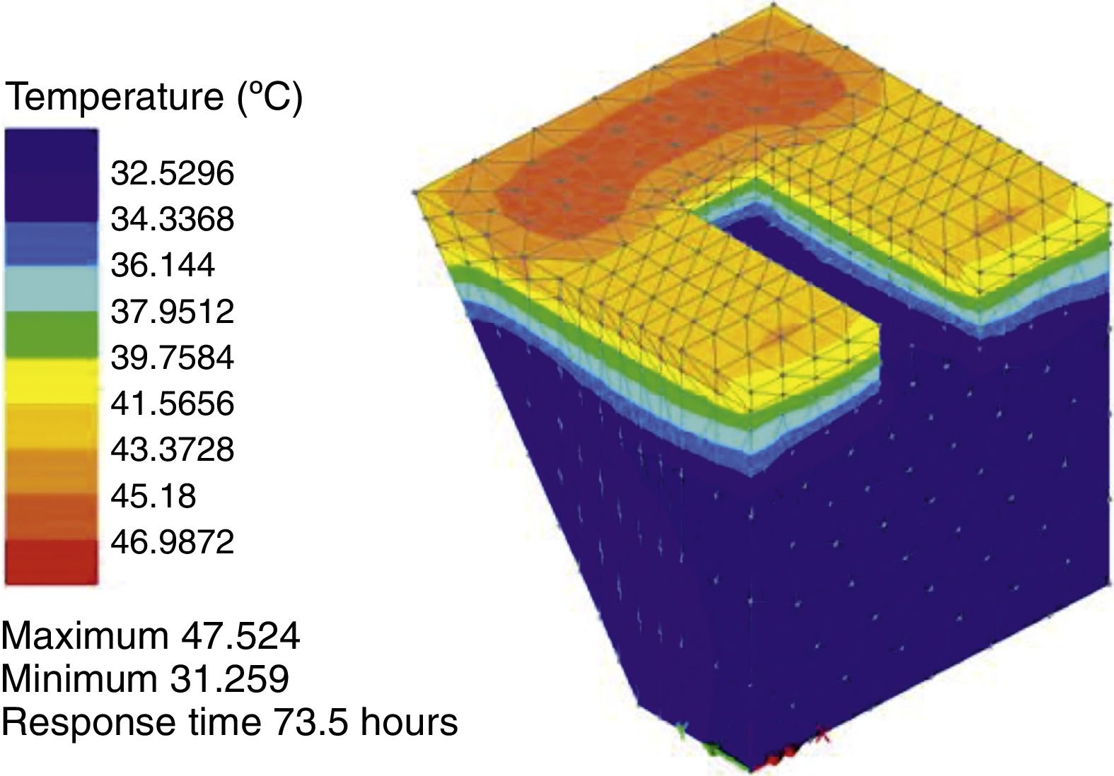
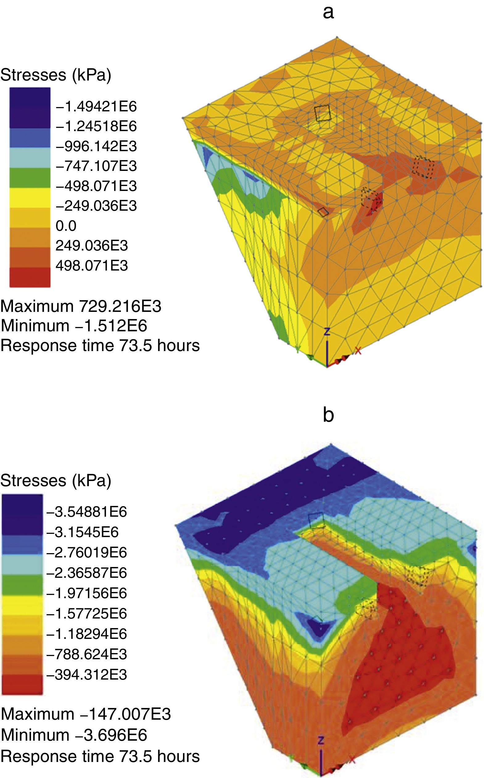
We present next the temperature profile (Fig. 19) in the RHC infill mix when the pour 2 is 90min old (pour 1 is 73.5h old) and the corresponding thermal stresses in Fig. 20.

 and minimum (b) principal thermal stresses in RHC infill concrete at 73.5h. There are a few thermal cracks in both pours 1 and 2; those in pour 1 are shown by broken pyramids.")
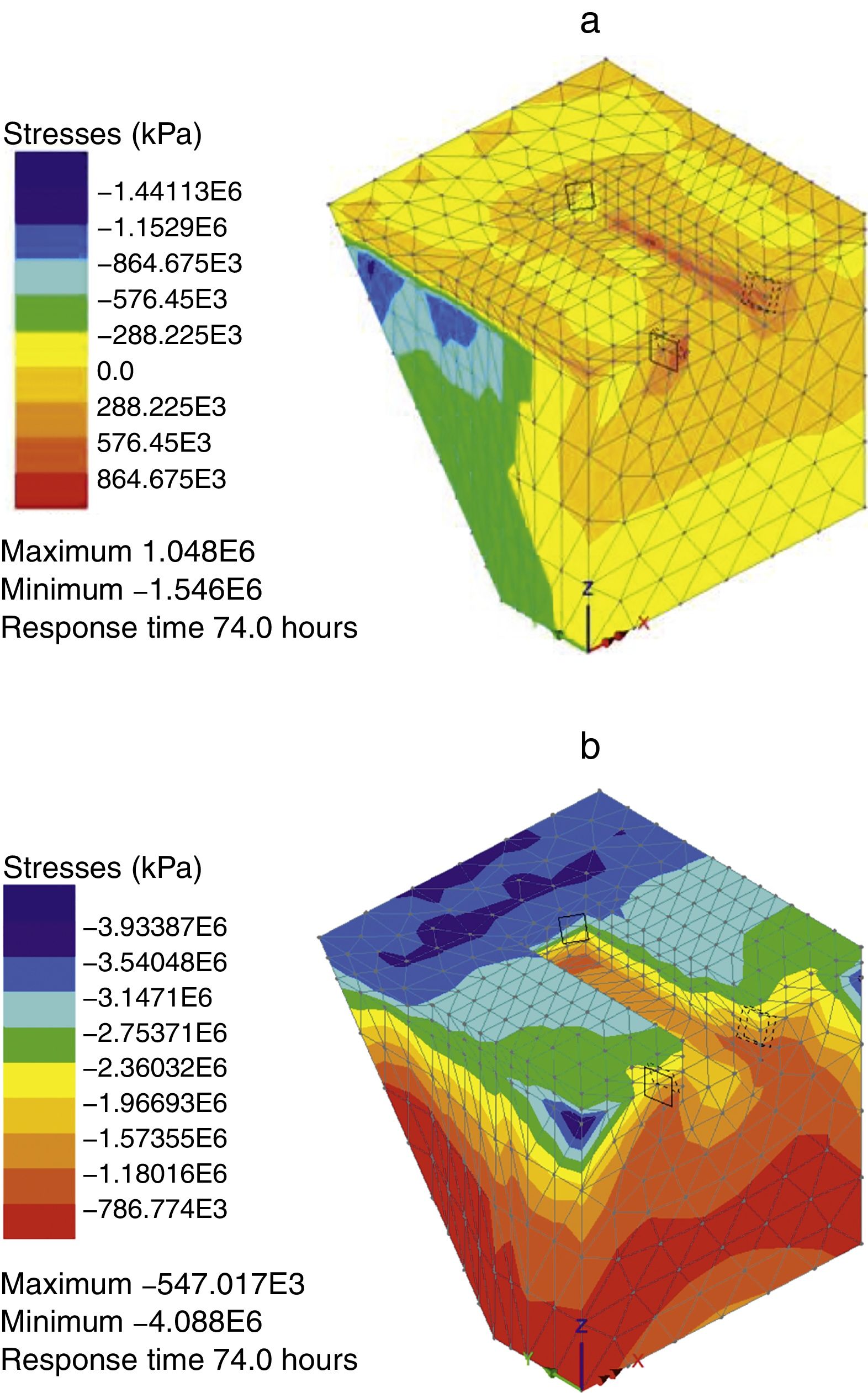
Finally, we show in Fig. 21 the thermo-mechanical stresses when the age of pour 2 is 120min and that of pour 1 is 74h.
 and minimum (b) principal thermo-mechanical stresses in RHC infill concrete at 74h.")
The minor cracking in both pours 1 and 2 is very nearly the same as at 73.5h (Fig. 20) which again suggests that cracking is primarily induced by thermal stresses.
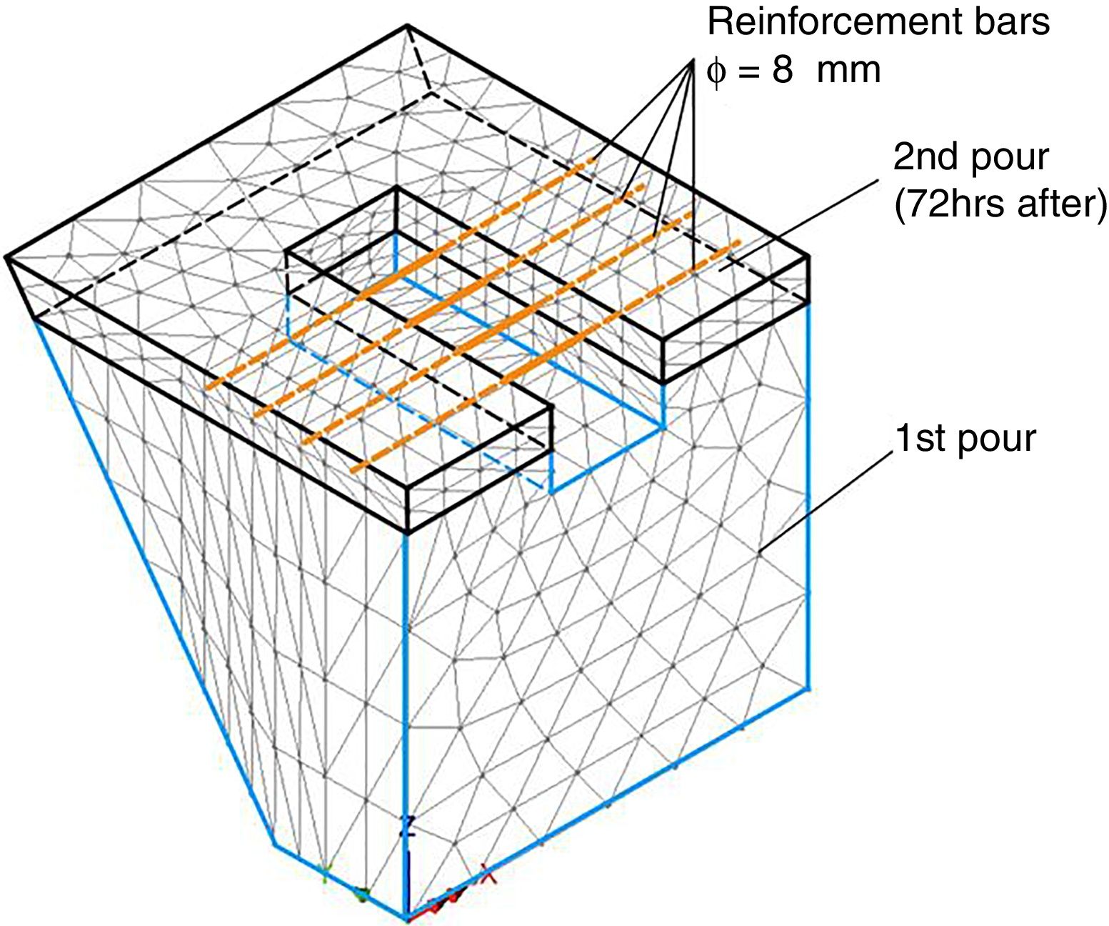
4.6Importance of thermal stresses to early age performanceIn order to demonstrate the importance of thermal stresses induced by the heat of hydration to the early age performance of the infill concrete elements, we have performed an inelastic analysis of the repair option 3 without thermal stresses. We were now able to include also the 4 rebars of the sleeper in this option, as shown in Fig. 22.

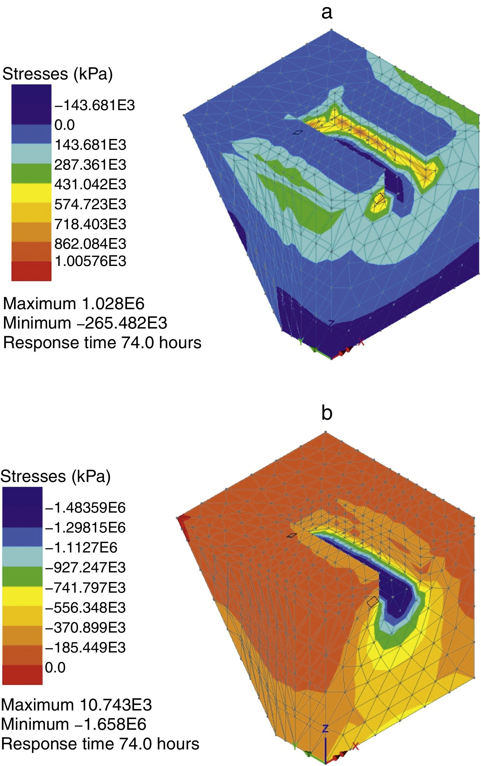
The principal mechanical stresses in the infill concrete at 120min age of pour 2 (pour 1 is 74 hour old) under the vertical wheel loading are shown in Fig. 23. A comparison with Fig. 20 clearly shows that the thermal stresses are responsible for most of the minor damage. Indeed, it would appear from Fig. 23 that the vertical wheel loading hardly causes any damage even at this young age.
 and minimum (b) principal mechanical stresses due to vertical wheel loading in the infill concrete when pour 2 is 120min age (pour 1 is 74h old). To get an idea of the role of thermal stresses in the early age performance, this figure should be compared with Fig. 21.")
Maximum (a) and minimum (b) principal mechanical stresses due to vertical wheel loading in the infill concrete when pour 2 is 120min age (pour 1 is 74h old). To get an idea of the role of thermal stresses in the early age performance, this figure should be compared with Fig. 21.
In the above thermo-mechanical analysis from 90 to 120min age of infill RHC concrete in all three repair options we considered only the most favourable mechanical loading scenario, i.e. when the wheel loading was vertical (total static equivalent vertical load=209kN). It is of interest to investigate the performance of RHC infill concrete when the full shear loading in the lateral (65kN) and longitudinal (1.6kN) directions are applied, besides the vertical loading. In our co-ordinate system (Figs. 5 and 11), the longitudinal, lateral and vertical directions correspond to x, y, and z axes. We shall demonstrate the influence of the full lateral and longitudinal shear loads on the repair option 2. Fig. 24 shows the principal thermo-mechanical stresses at age 120min, i.e. 30min after the application of the wheel loads. A comparison with the corresponding thermo-mechanical stresses under vertical wheel loading only (Fig. 15) shows that the lateral loads do indeed induce additional damage to the infill RHC concrete.
5Conclusions and minimum (b) principal stresses.")
- •
The RHC mix easily reached the supplier's specified characteristic strength data at all ages at which we tested it.
- •
The thermal analysis of the hydrating infill RHC concrete in repair options 1 and 2 shows that the thermal stresses are the primary cause of early age (up to 120min) damage (cracking) even after the wheel load comes on the sleeper. The infill concrete made from the RHC mix is able to withstand the thermal and thermo-mechanical stresses with minimum damage in both these repair options.
- •
The repair option 3 in which the RHC infill is cast in two pours with a 3-day interval shows more thermal damage, especially at the interface between the two pours.
- •
Lateral shear loads, besides the vertical wheel load, cause some additional damage.
HC would like to acknowledge financial support provided for this research by the Spanish Ministry of Science and Technology under project BIA2016-75431-R. This work was completed during HC's sabbatical at Cardiff University.