


The Trapagaran viaduct was divided into 3 parts: main viaduct, access viaduct and transition area. The main viaduct is 670m long with 125m spans. It is formed by a 35.60m wide, 5.90m deep prestressed concrete box cross section. The access viaduct is formed by four separate structures with spans reaching 86m. Each of the decks is made up of a composite 3.50m deep box girder. The four branches converge in the transition area displaying complex geometry. The transition area is a prestressed concrete structure of approximately 60m in span executed on falsework.
El viaducto de Trapagaran se divide en 3 partes: viaducto principal, viaducto de acceso y zona de transición. El viaducto principal tiene una longitud de 670m y vanos de 125m. Consta de una sección cajón de hormigón pretensado de 35,60m de ancho y canto de 5,90m. El viaducto de acceso está formado por cuatro estructuras separadas, con luces que alcanzan los 86m. Cada uno de los tableros está compuesto por una viga cajón mixta de 3,50m de canto. Los cuatro ramales convergen en la zona de transición que presenta una geometría compleja. La zona de transición es una estructura de hormigón pretensado de unos 60m de luz ejecutada sobre cimbra.
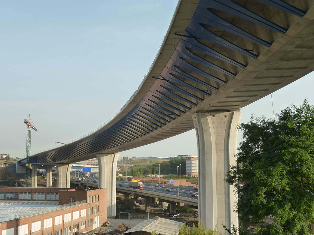
The Trapagaran viaduct comprises the works of the South Metropolitan Bypass of Bilbao (SMB) and serves as a connection between the link with the A-8 motorway and the initial stretch of the SMB main alignment. This is a singular project, given the size and characteristics of the viaduct, plus the lower obstacles it crosses. The proposal was for an appropriate solution adapted to its structural and aesthetic importance and to its integration within the environment.
2Design constraintsThe design constraints for the Trapagaran viaduct are multiple and range from the actual layout of the SMB to the effects on existing buildings and roads, the appearance of the structure, the completion timeframe and its cost. The following sections provide a detailed description of these constraints.
2.1AlignmentThe viaduct, which measures 995m, starts at the Trapagaran junction, engaging with the main body of the motorway and its various branches, rising to a single, large-sized platform above the neighbourhood of Trapagaran–Causo towards the toll area.
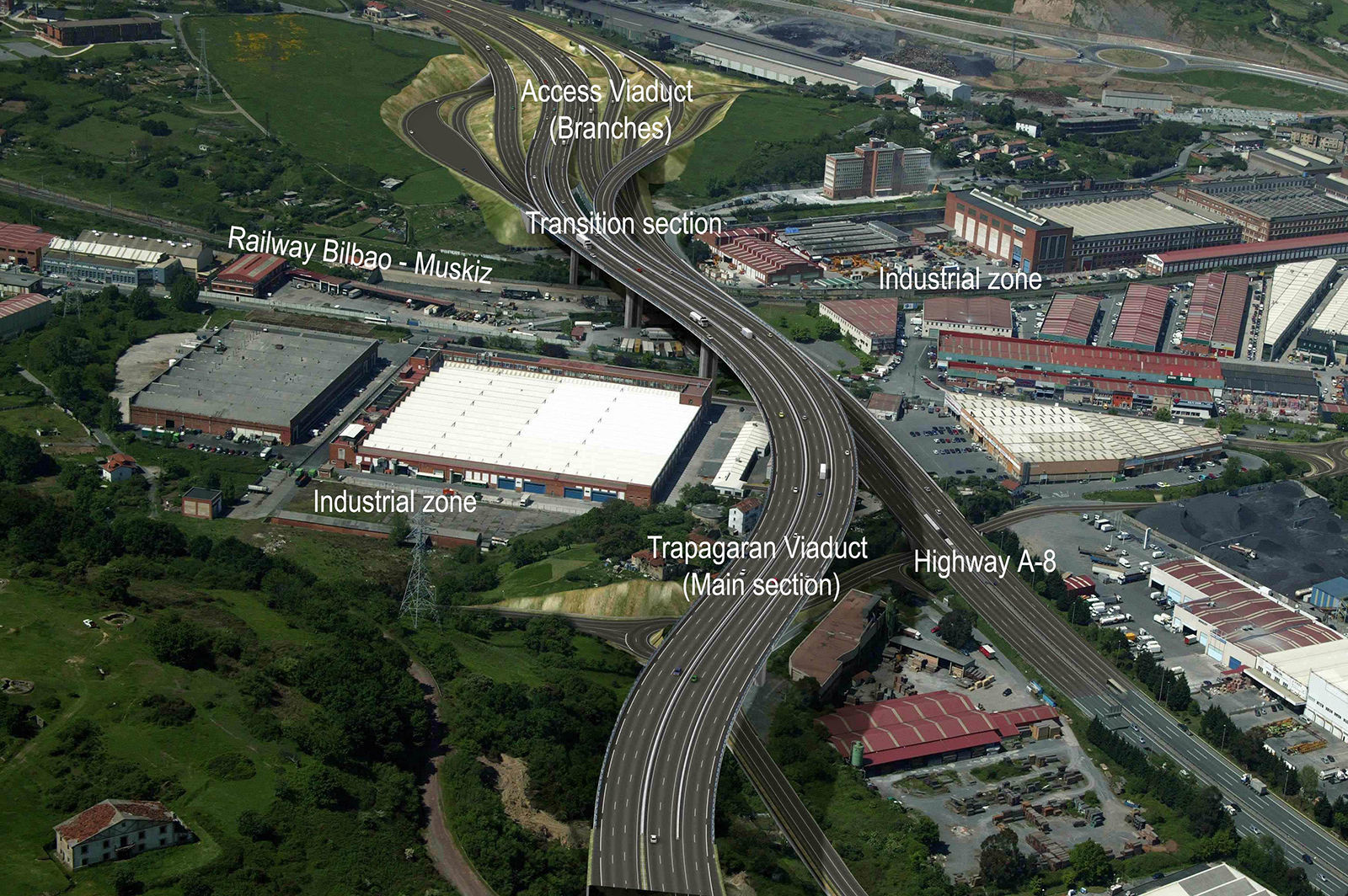
This layout creates 3 quite different parts of the viaduct (Fig. 1):
- •
The approach viaduct, where each of the four branches of the junction converge onto different decks.
- •
The transition stretch, located between the main viaduct and the approach section, where these branches come together to join into a single deck.
- •
The main viaduct, where the 3 different SMB roads run along a very wide single deck.

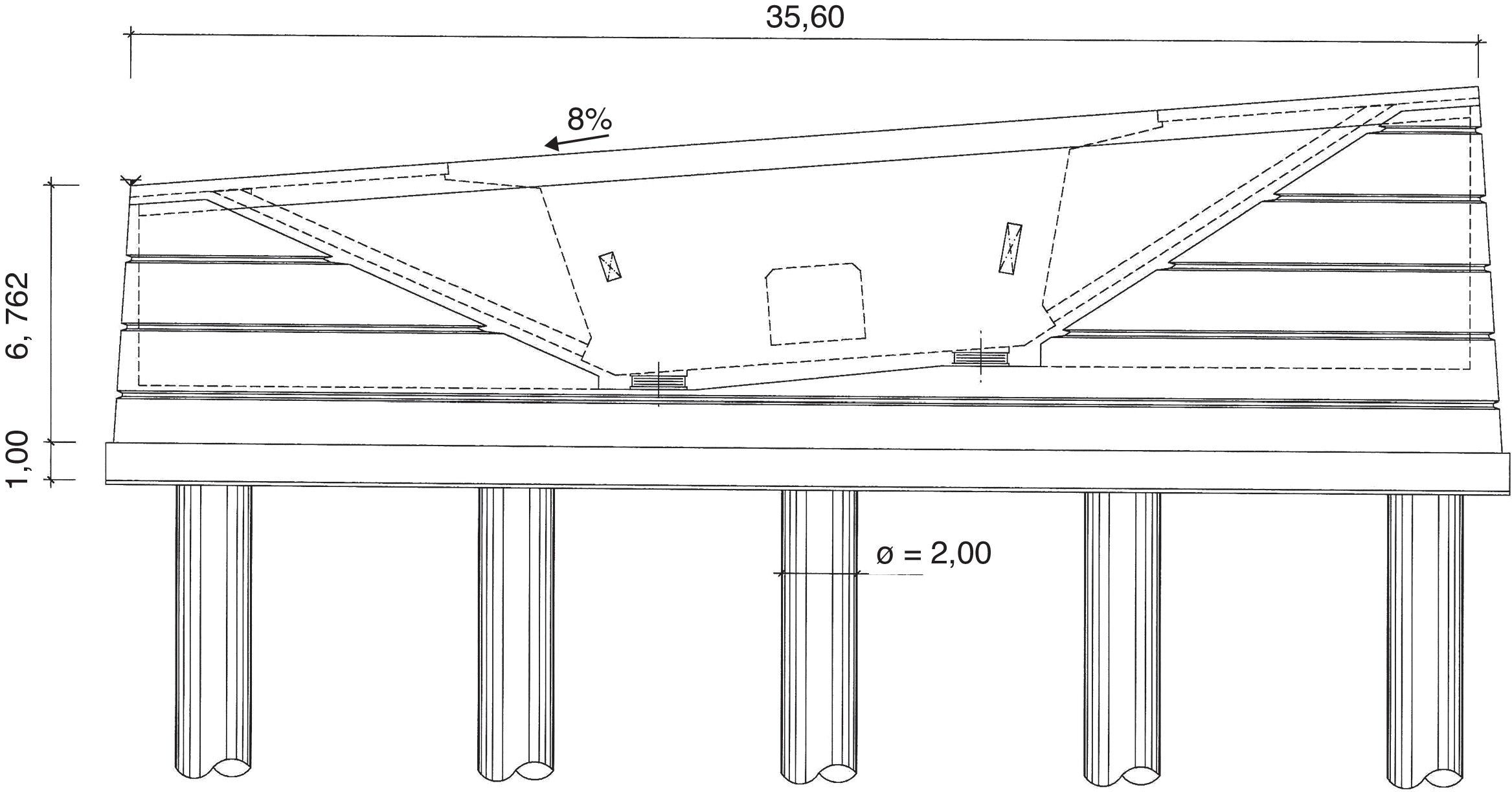
In the main viaduct area, the SMB runs along a curve and a reverse curve, linking up to 7 different alignments within the structure. These designed curves have a minimum radius of 500m. Due to the existence of severe radii of curvature, the cross-section bank reaches 8% in some places. The maximum height of the deck over the natural terrain is around 42m. The SMB main alignment road over the main viaduct has 3 different roadways, two 9.50m wide descending ones and another 13.5m wide ascending one. Therefore, the whole deck measures 35.60m wide, including barriers and railings.
In the approach viaduct, the intersections of the various branches over the A-8 roads run in a curve and with a pronounced skew. Furthermore, the traffic on the A-8, running under the deck of the viaduct, has forced choosing a suitable structural typology as a whole, in such a way that the construction least affects that traffic.
2.2InterferencesIn the viaduct area, the SMB must successively cross over the Bilbao–Muskiz railway line, and the BI-745, BI-3746 and N-634 roads. In addition, the viaduct runs through an industrial area. Therefore, the piers are sited so as to preserve the existing buildings to a maximum. An appropriate construction procedure was chosen to minimize, as far as possible, anything affecting the business of these industries. Bearing in mind that there were low-lying obstacles in the area, it was deemed convenient for the main viaduct to be designed with a span of 125m.
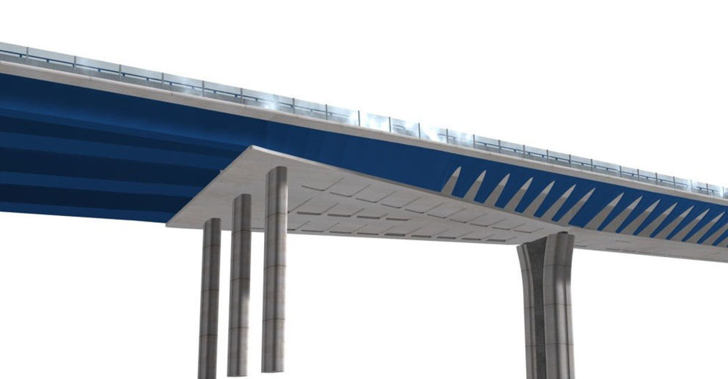
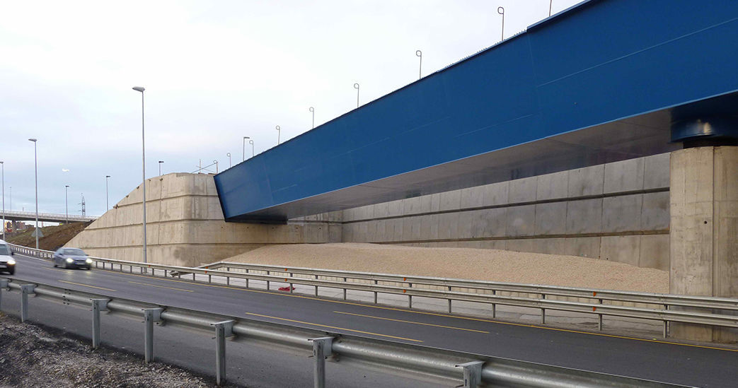
2.3AestheticsThe height it runs at, the size and how close it is to the A-8 mean that its visual exposure level is extremely high. Therefore, the design requires an elegant viaduct, integrated into the environment, and at the same time avoiding the disposition of any heavy, striking or intrusive structures.
2.4ConstructionDue to the multiple low-lying obstacles mentioned above, whether roads or buildings, constructing the deck of most of the viaduct should be done from the structure itself. The construction system had to be suitable for the range of spans for the main viaduct, and the varying curvatures on site.
Finally, building the complete viaduct had to be finished within 32 months so as not to compromise the inauguration date of the whole SMB.
2.5EconomyAlthough we tried to design an elegant and aesthetic viaduct, the final cost of the structure had to be within reasonable ratios per square metre for this category of viaduct.
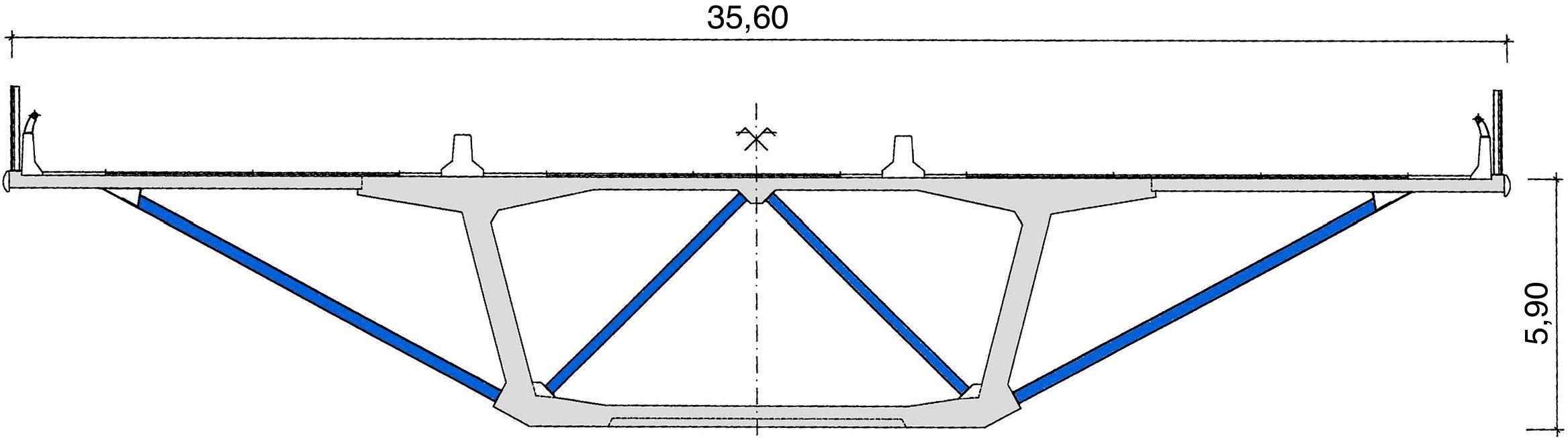
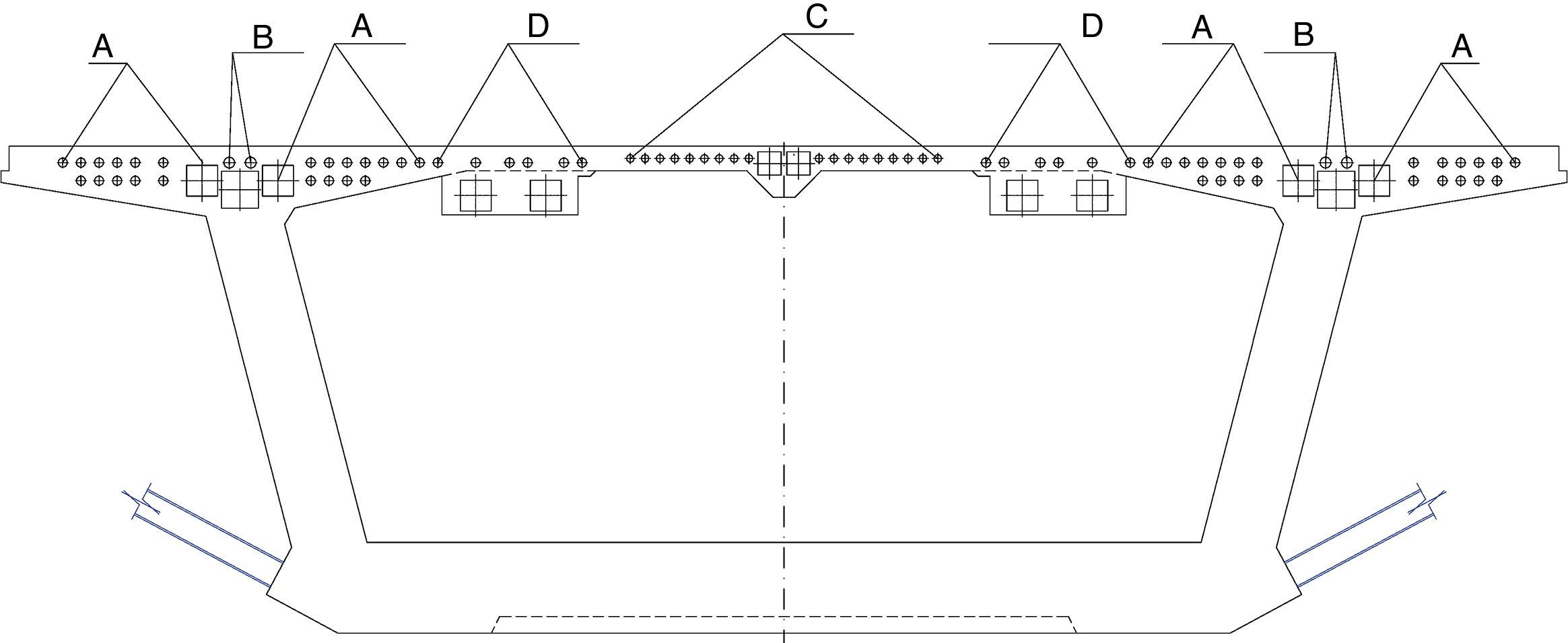
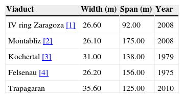
3Initial design criteriaThe first initial design criteria are based on the intention to minimize the encumbrances for the buildings and firms located in the industrial area. This prompted choosing a single deck (Fig. 2), measuring 35.60m wide, resting on single-shaft piers for the main viaduct. The magnitude of this width greatly exceeds normal figures for single-deck viaducts with 3 road lanes. Values are normally around 26.00m (see Refs. [1,2,4]). Generally speaking, the section of these decks is defined by a resistant core or box and various wide side cantilevers resting on brackets or transverse beams.

Widths over 30m are normally resolved for conventional viaducts by the juxtaposition of the various box girders equivalent to the normal deck width of 10 or 12m. These widths usually correspond to large hanging or cable-stayed viaducts, which are supported at the two deck edges. This lateral support makes it necessary to define a transverse section made up of trusses or by a multicellular box. For this reason, during the project design phase, the choice of deck of a box girder type scheme with a single deck beam was a challenge in this important issue.
Among the references for classic beam-type, prestressed concrete, large-sized viaducts, solved by using a single web, we can bring attention to the Kochertal viaduct measuring 31.00m and the Felsenau one of 26.20m (Table 1).
The second initial criteria adopted for designing the viaduct was that, in spite of its geometric complexity and the variability involved due to the layout, each part should not be designed separately or independently. The whole assembly had to give an overall image with a certain formal unity over the complete viaduct.
4Main viaduct deck4.1General descriptionThe deck of the main viaduct is a continuous beam with a length of 670m, divided into 4 central spans of 125m and two ends spans measuring 90 and 80m.
As already mentioned, the deck has a width of 35.60m with room for 3 different roadways, two ascending ones 9.50m wide with two lanes and hard shoulders and another descending one with 3 lanes and 13.50m wide. There are 0.60m wide rigid barriers between them, whereas there are 0.50m wide parapets at the ends. At the beginning, near the transition area, there is a slight variation in width that reaches up to 36.34m, which has been overcome by changing the length of the side cantilevers.
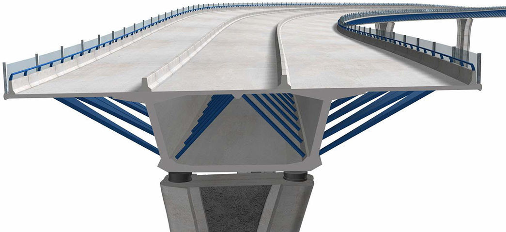
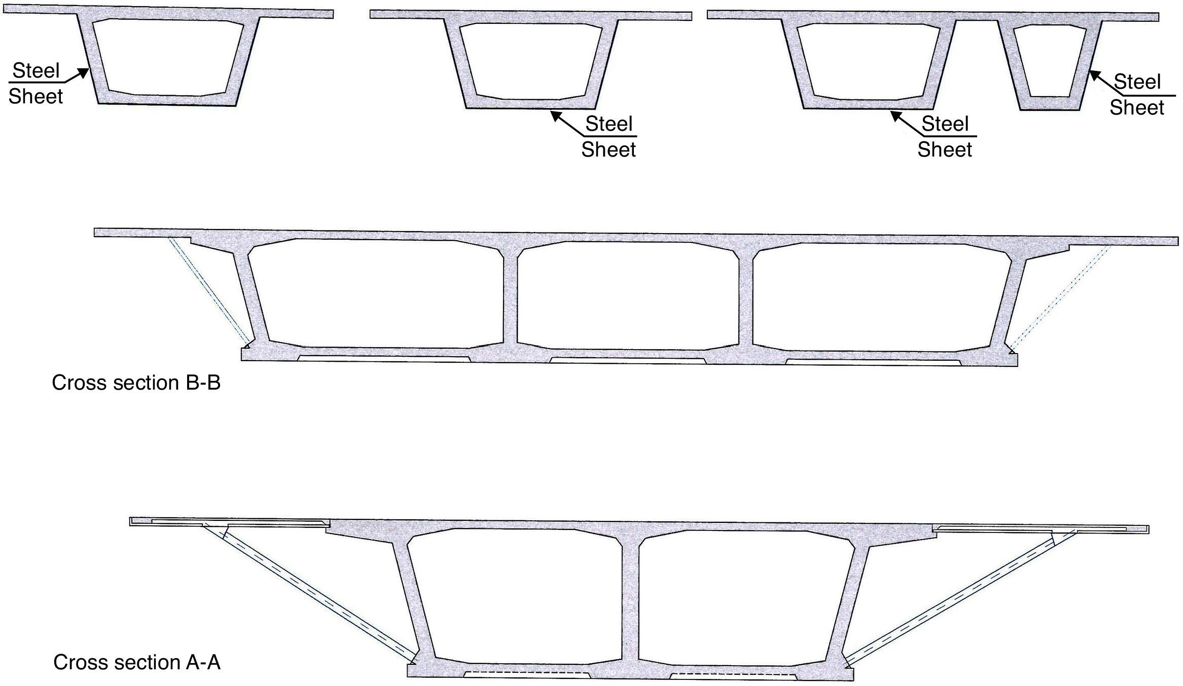
The deck structure was resolved by a single resistant box girder or core made of prestressed concrete, which, with a constant 5.90m depth, perfectly adapts to the variations of curvature and bank. The central box girder has an upper width of 19.00m, completed by some side cantilevers that rest on transverse braced box girders (Fig. 3). The box girder webs are 0.60m thick in most of the spans and increase to 0.90m near the pier supporting areas.

The use of side braced box girders not only permits achieving large side cantilevers, but also creates sloping side planes that disguise the magnitude of the deck edge. Furthermore, the outer braces form a triangulation of the transverse section that continues inside the box with other steel tubes. This triangulation allows shortening the transverse spans of the upper deck, facilitating the arrangement of slabs with a lower thickness.
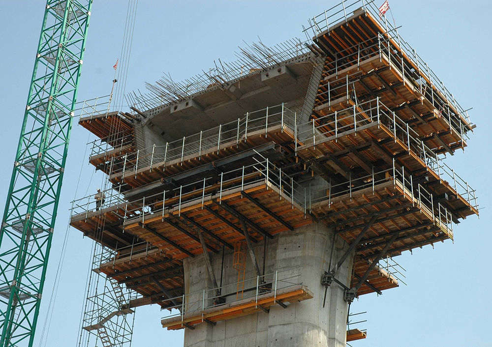
The deck was built in two stages. In the first phase, the core of the section (19.0m wide) was built by balanced cantilever, advancing symmetrically from the piers (Figs. 4 and 5). Only the first 30m and the last 20m of the respective end spans of the main deck were constructed using falsework that rested on the ground. All the segments measure 5.00m long, keeping pace with the side braced box girders.


In spite of a 125m span and using the balanced cantilever method, there is a constant depth so as to provide good vision of the viaduct, much better adapted to the changes in curvature and camber of the stretch when using the typical solution with variable depth.
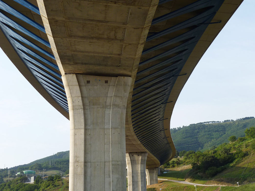
The lower part of the core has transverse beams that coincide with the segment fronts, by way of prolonging the support of the side brackets. This gives a coffering appearance to the underside of the deck. The lower deck is 0.30m thick and this increases to 1.20m at the pier section. At all times we sought to favour the lower appearance of the viaduct, since it will be seen mainly from the industrial area, that is to say, from below (Fig. 6).

Having completed the continuous girder forming the core, the side brackets and precast slabs were mounted at each end, using cranes that move around on the deck itself, until reaching the total width of 35.60m.
4.2PrestressingThe longitudinal prestressing of the main viaduct is broken down into 4 families for the upper slab and into one for the lower slab (Fig. 7). The first 3 families are arranged according to the actual structural requirements for the balanced cantilever method:
- •
Family A comprises 48×25T15 tendons for each double cantilever.
- •
Family B is a reinforcement of 6×37T15 tendons arranged in the core areas for the first segments.
- •
Family C comprises 20×13T15 tendons that are anchored in the central beam area used to support the interior tubes.

The fourth family, D, of the upper prestressing comprises 16×24T15 tendons anchored in blisters arranged on the upper deck in the first 3 segments. While conscious of the difficulty at formwork level on the upper slab that these blisters involve, they were all designed in identical positions and in the same size.
The tendons of family D are stressed once the transverse section of the deck measuring 35.60m wide has been completed. In evolutive sections, there is normally an external continuous prestressing with polygonal shape, once construction has been completed, in order to transmit uniform compression to the whole section. However, in this viaduct, we chose to do without the external prestressing, due to the existence of interior sloping tubes that greatly impeded the layout.
Continuity prestressing of the lower deck is achieved by using 32×19T15 tendons in the central spans and by 24 and 16×19T15 tendons in the first and last spans, respectively.
The transverse prestressing comprises 4×4T15 bonded tendons for every 5.00m segment, covering the whole width of the deck. They have a flat duct and the anchors are placed on the prefabricated slabs.
The prestressed tendons with flat ducts are frequently used in the floors of buildings, because they combine the advantages of bonded prestressing and limited vertical sizes of the unbonded strand post-tensioning tendons. In the case of the Trapagaran viaduct, due to the evolutive character of the transverse section, it was appropriate to install these tendons, although without placing the strands in the first phase, which is contrary to what happens in buildings. Aware of the fragility of the flat ducts, which are very sensitive when trodden on and to the impact that might be made during concreting, these were mounted on site with 2×20mm supporting reinforcement bars and 4 shorter sacrifice cable strands that were used from one segment to another. These measurements largely preserved the integrity of the ducts. However, in spite of this, there were damages forcing the repair of some ducts that were blocked or squashed, with consequent slab repairing operations. From experience, we can deduce that it is preferable to increase the slab thickness by a few centimetres and use tendons with circular ducts.
4.3Core constructionConstructing the core began by implementing Segments Zero on piers, which are 10m long. To do this, brackets were used that rested on the openings left on the top of the pier (Fig. 8). Completion of each of these segments lasted 6–7 weeks.

Three pairs of 350t capacity form travellers were used to build the cantilevers. Normally a couple of segments are produced every week by a pair of travellers. However, in weather-favourable times of the year, production reached 3 couples of segments every two weeks using a pair of travellers. Two or three weeks are required for the end segments.
The segments were built without any interior bracing. These were placed afterwards so as not to impede the manoeuvres of the form travellers. To do this, the top slab of the box was designed to have sufficient flexural strength to support the actual weight and construction overloads with the transverse span, determined by the distance between the webs of the box.
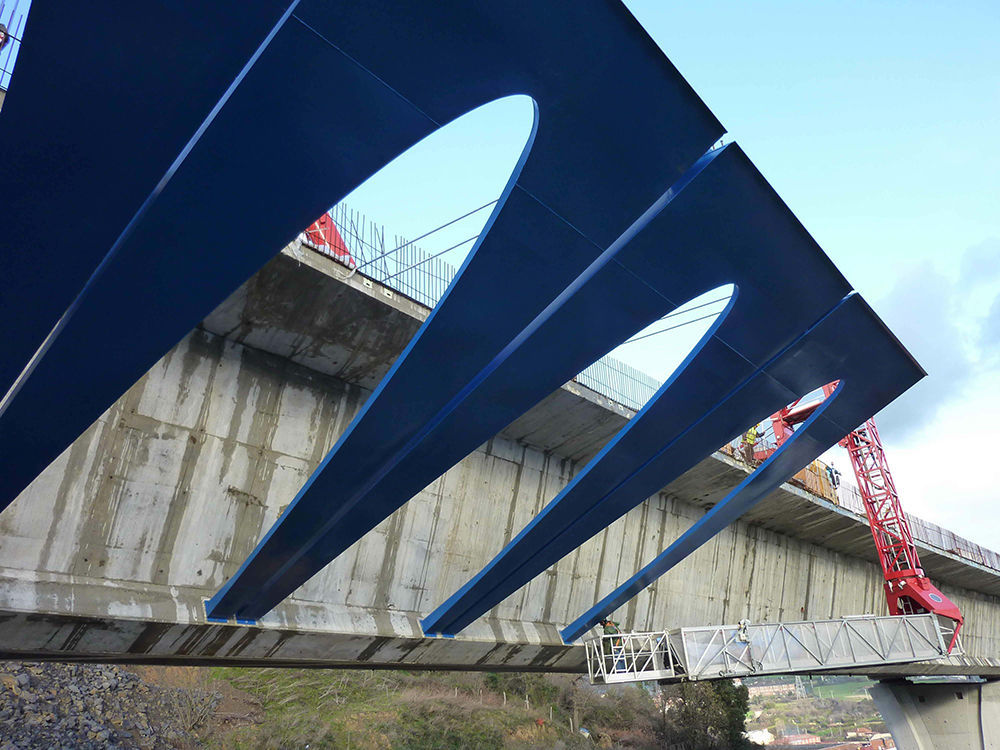
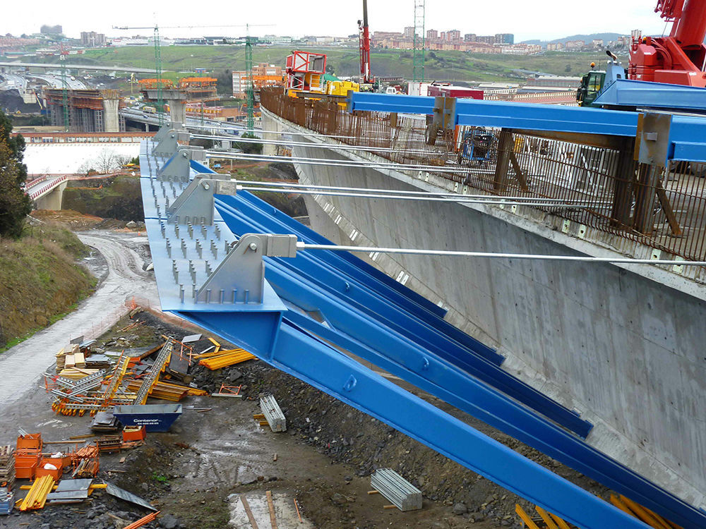
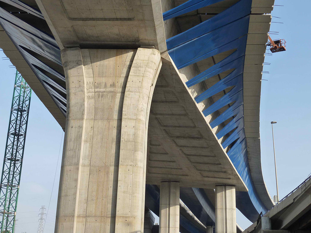
4.4Side cantilevers4.4.1Exterior side bracketsThe exterior side brackets are steel portal frames covered on the outside by 6mm thick cladding with a parabola-shaped opening to improve appearance (Figs. 9–11). It was expressly decided that they should be steel to obtain, through texture and colour, the effect of a formal unit along the whole viaduct, including the transition and the approach viaduct. In addition, in the area of the main viaduct, its contrast with the concrete breaks the monotony of an excessive width and lightens the view below the deck.


The side brackets have a structural portal scheme and are arranged in 5.00m wide×10.60m long modules. Their jambs are made up of square hollow tubes measuring 300×300×12mm separated by 4.40m from each other. The lintel is a triangular-shaped beam that is hidden by the plane formed by the decorative cladding. Continuity is not established between the lintels of consecutive portals.
To industrialize production and help the on site layout, all the portals have the same centre-to-centre distance along the viaduct, regardless of the fact that they are inside or outside the curve. For this reason, the decorative cladding varies in size with a visual slot between similar-sized braces along the whole bridge.
In areas where there is constant bank, the lower faces of the jambs and lintel are in the same plane. However, in the banking transition areas, there is a slight distortion of the frame displacing the end of one of the footings some 40mm with respect to the other one. Inserting a flat element of this size is geometrically incompatible with varying bank. Where this distortion has not been provided, a clicking is observed between the upper edges of the contiguous portal side brackets.
We should point out that, considering these measurements, together with the efficient work of the geometric definition by the steel workshop and the meticulous placement by the site workers, this allowed for an excellent finishing (Fig. 12).

The connection between the side brackets and the top slab was carried out using Nelson type studs. These studs were arranged so that they freed the beams and reinforcement of the precast slabs.
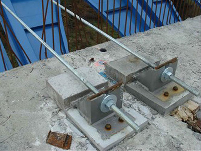
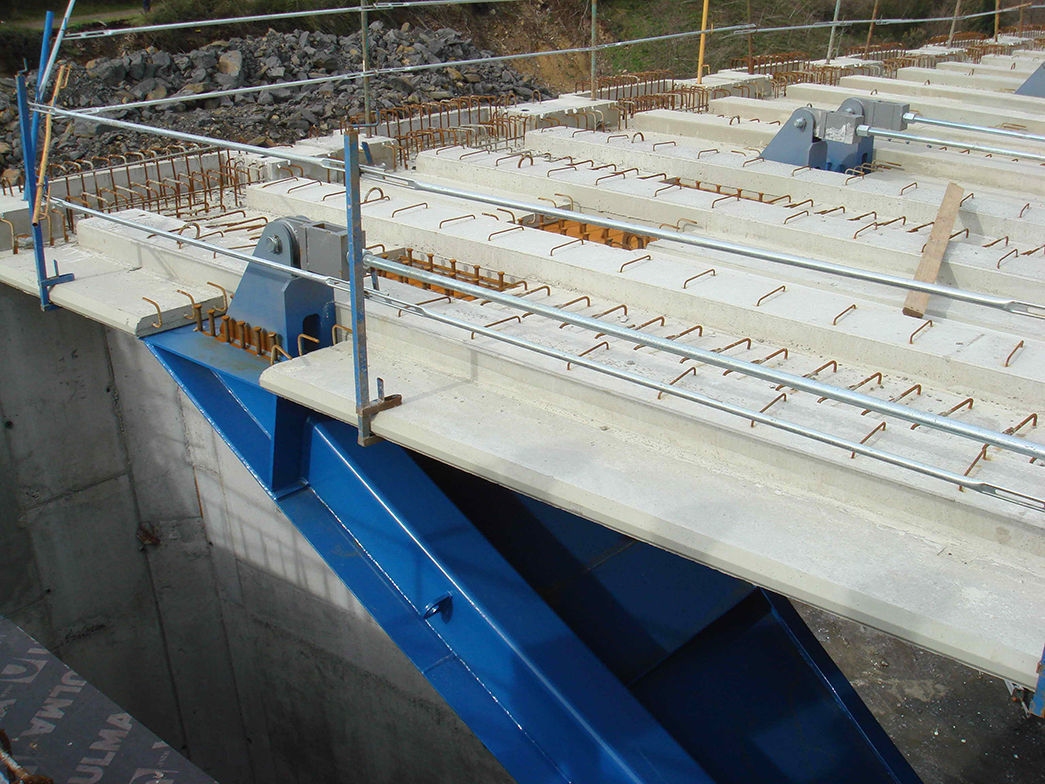
4.4.2Side brackets fixing systemDuring construction, the upper part of each portal frame is provisionally held by two passive bars anchored to steel plates, placed on top of the frames, and to steel fixing pieces connected to concrete blocks that protrude from the deck core (Fig. 13). The bars are made of F-1252 quality steel, 36mm in diameter. These bars are separated from the upper surface of the deck to help placement of the precast slabs (Fig. 14). The bars, as well as the steel pieces joining the deck, have been re-used throughout the whole deck construction.


On the lower part, the side brackets have a steel block introduced into a square hollow left in the box core. The support sheeting is coated with epoxy resin just before placement to ensure good contact to the lower part of the legs.
4.4.3Precast slabsTwo precast slabs measuring 2.50m wide×8.40m long rest transversely on every portal frame of the side brackets and small corbel left in the core. The precast slabs incorporate the anchors of the transverse prestressing plus all the built-in elements required for safety during construction.
The vertical distance left between the braced box girders and the provisional fixing bar system, as well as an earlier analysis of all the possible geometric interferences, has allowed for rapid and simple mounting of the precast slabs.
Having placed the reinforcement bars and cast the concrete in the slab of the side cantilevers, the transverse prestressing tendons are made up of 4 x 4T15 units for each portal side bracket. These tendons cover the whole width of the deck. The final thickness of the side cantilever slab is 0.30m.
Once the transverse prestressing has been done, the stress is released from the fixing system bars. The steel wing plates protruding from the portal side brackets are cut and the concrete blocks in the core of the deck are demolished.
4.4.4Assembly and performanceAssembly of all the side brackets was carried out by a single crane and with the help of a lorry fitted with an articulated platform, which allowed access to the base of the box. Both vehicles drove on the core of the deck that had been constructed beforehand. Therefore, this second phase caused hardly any inconvenience either to the traffic below or to the activities of the neighbouring industries (Fig. 15).

Production for placing the side brackets reached 8 units a day, whereas mounting the precast slabs was between 30 and 40 units a day.
Concreting the side cantilever slab was carried out in 40m long sections once the reinforcement bars had been installed and the tendons of the transverse prestressing inserted.
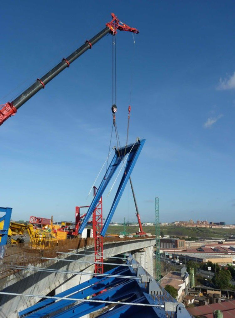
5Approach viaduct deckOn the approach viaduct, the crossings of the different branches over the lanes of the A-8 are curved and with noticeable skew angle, which forces having spans in excess of 70m. On the other hand, traffic on the A-8 meant choosing a type of deck, the construction of which least affected the motorway traffic that was in service. For this reason, a type of composite deck was chosen for this area.
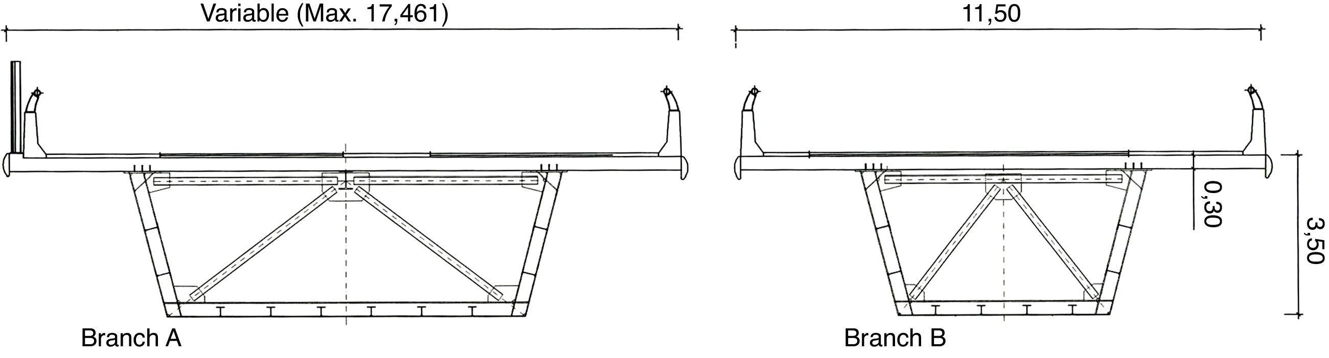
The approach viaduct is made up of four different branches with the following widths and spans:
- •
Branch A. Width=var. 11.80–17.40m. Spans=56.71+79.23+76.98+59.25
- •
Branch B. Width=11.50m. Spans=37.99+77.04+52.26+59.80
- •
Branch C. Width=11.50m. Spans=42.02+86.43+43.47+53.50+60.25
- •
Branch D. Width=7.80m. Spans=54.57+61.10
For these 4 branches with the indicated spans, the one that corresponds to the last span and the 12 previous ones belong to the so-called transition area. Each deck comprises a composite concrete and steel section box. All the steel box girders have a 3.20m edge and a top slab of 0.30m thick reinforced concrete, cast in situ on precast slabs (Fig. 16). It was decided for aesthetic reasons that branch A, which varies greatly in width, should maintain a constant width of the cantilever and therefore absorb this variation with the steel box girder.

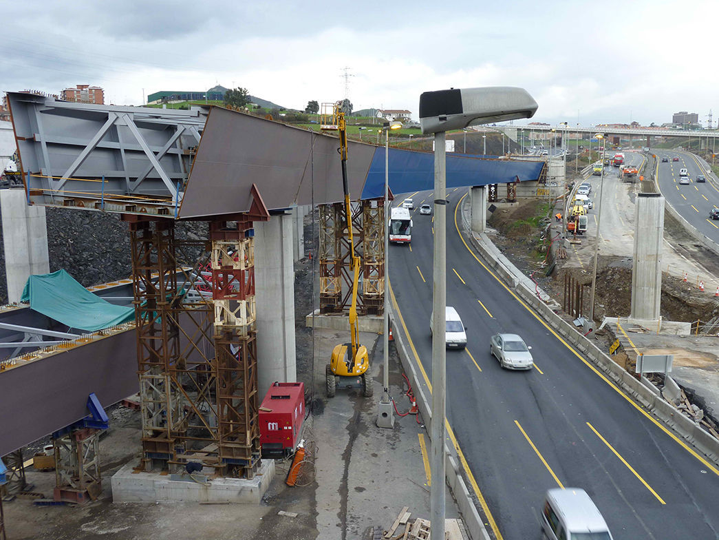
For branches B, C and D, assembly could be undertaken without any traffic below. Fig. 17 shows the steel box girders of branches B and C on provisional supports. Erecting these temporary supports was such that traffic was allowed to run on the A-8 in the Bilbao way before the transverse cross section was completed. However, mounting operations for branch A had to be carried out at night when the A-8 was cut off avoiding intermediate bearings, a complete segment measuring 76m was hoisted in a single operation.
6Transition area deck6.1Preliminary considerations
The approach viaduct comprises a series of 4 branches that come together on the deck of the main viaduct in a transition area, the most significant peculiarities of which are summarized below:
- •
Complex geometry in the confluence of different alignments.
- •
Variable curvature. Two variable and different banks on the top platform.
- •
Variation of deck width from 36.34m at the beginning of the main viaduct to 40.80m in the start section of the branches of the approach viaduct.
- •
Variation in depth ranging 5.90m of the main viaduct to 3.50m of the approach branches.
- •
Change from a single box with side brackets and wide side cantilevers to four independent box girders.
- •
Change from prestressed concrete resistant material to a composite structure.
The design required special treatment for keeping the harmony of the whole unit and its aesthetic qualities, thus avoiding any sudden variations in fundamental forms.
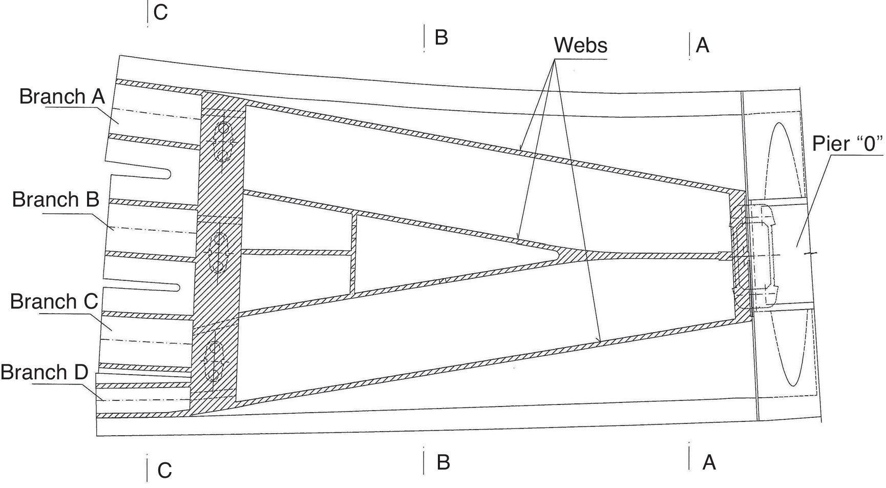
6.2GeometryThe deck in the transition area was resolved with a multicellular section of prestressed concrete starting from pier 0 with the same section as the main viaduct, but with an additional central web. The central web divides at a third of the span into two cores in order to reduce the transverse span of the upper deck (Fig. 18). The depth changes linearly from 5.90m on pier 0 up to 3.95m in a section located 5.00m of the axis of piers P-1A, P-1B and P-1C. This forms a sudden jump in depth from 0.45m at the front. After this section, the lower view of the deck appears as 4 boxes and not as a single one.

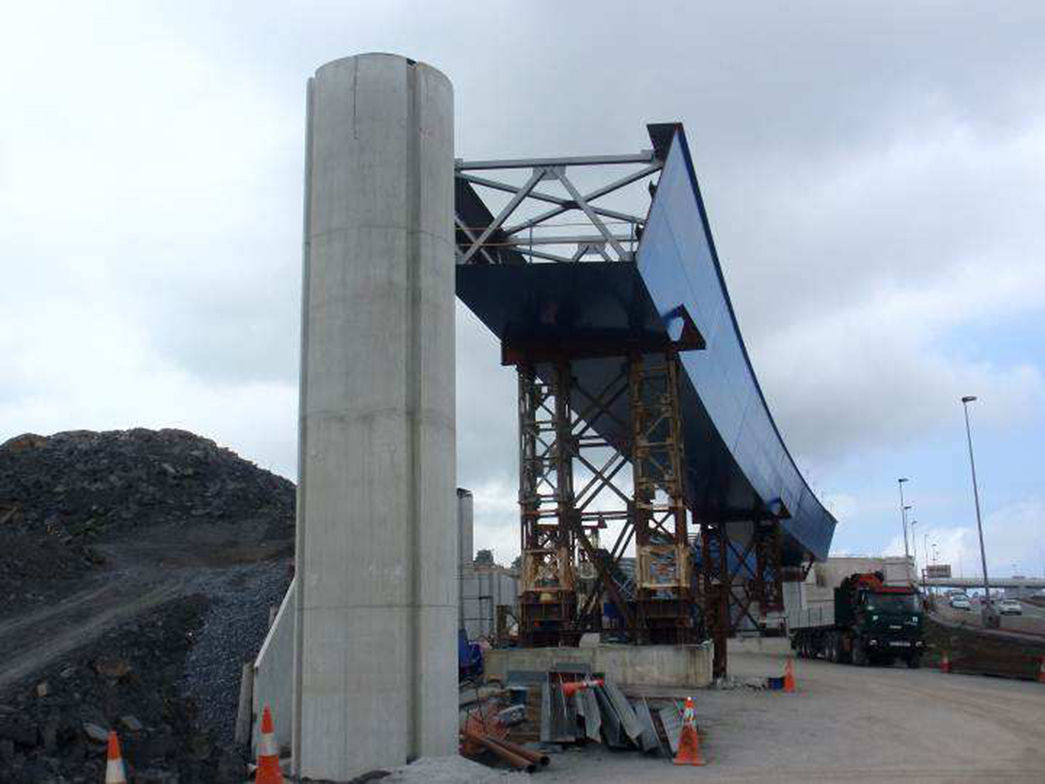
On the 3 piers in the broad part, there is a very powerful transverse diaphragm for connecting the transition area of variable width with 4 boxes of prestressed concrete (Fig. 19). These boxes are defined by some sections with identical contours to those of the composite box girders of the approach branches to which they are connected. The box girders of prestressed concrete in the transition area have their web and the lower slab covered with decorative steel cladding.

The lower part, with clear and forceful geometry in the shape of a spatula (Fig. 20), also presents some ribs as in the main viaduct, which mark the different longitudinal structural ones. It connects with the structural continuity of the branch decks without any need for expansion joints. Only an expansion joint is required between the transition area and the main viaduct.

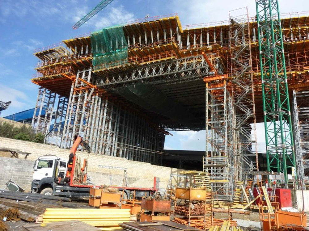
Due to its geometric complexity and given that the clearance over the railroad so allows, this area was built in situ on falsework that rested on the ground (Figs. 21 and 22). To construct the shuttering, a 3D model was made of the whole concrete contour of the transition area. This model was contrasted with the one made by the subcontractor in charge of the falsework.
6.3Prestressing

Prestressing of the transition area is made up of 4 families of 6×24T15 tendons that pass through the main web with a parabolic layout. The webs of the 4 independent boxes, which serve to link the composite boxes and which do not prolong in anyone of the 4 cores of the main span, are also prestressed with 3×24T15 tendons. In addition, there are 14×15T15 tendons in the lower slab and 16, 4, 8 and 8×19T15 tendons in the top slab, in the negative area, for branches A, B, C and D respectively.
The diaphragm on the 3 piers was pretensed transversally with 20×7T15 tendons.
6.4Side cantileversThe side brackets in the transition area are warped from where they join the main viaduct up to where they join the outer webs of the section of the boxes of the end branches. They continue their structural function after the first few metres from pier 0. However, as they approach the 3 piers, the cantilevers noticeably diminish and become merely decorative.
When the size of the actual side brackets is reduced, the parabola-shaped opening is eliminated, leaving a closed surface for soft transition with the cores of the steel box girders (Fig. 23).

The side brackets and decorative cladding in the transition area are pieces similar to those of the main viaduct, with the same provisional fixing system. Due to the geometric variation in this area, they are all spatial elements that had to be designed individually.
6.5Approach viaduct connectionThe connection point between the 4 prestressed concrete boxes and the corresponding composite ones are arranged 12m away from the bearings on the piers, where the bending moment is more limited. Thus, the connection between the steel and concrete parts is fundamentally a shear one. This connection was made by using Nelson-type studs welded in a 3.00m long steel segment placed on the formwork in the transition area and where the concrete of the transition zone was poured (Fig. 24). Each of the remaining length of the 4 prestressed boxes was also covered with connecting decorative cladding, but with no structural function.
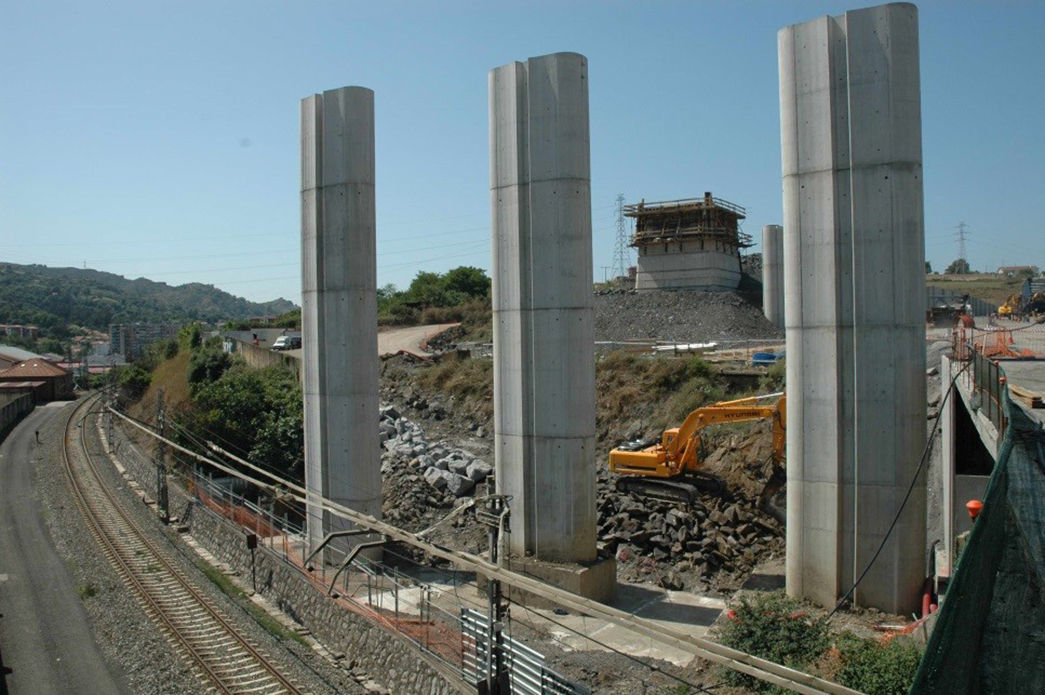
7Piers7.1Main viaduct piers
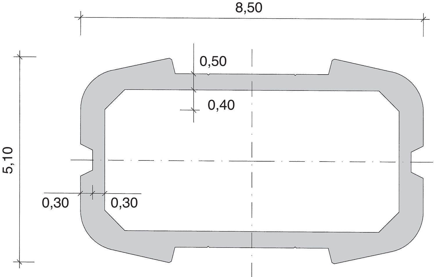
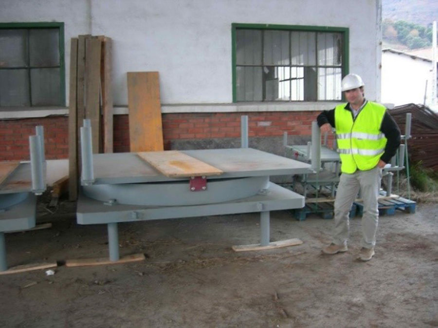
The fact of having arranged a single resistant core in the deck of the main viaduct allows defining piers that are contained as much as possible, resulting in minimum encumbrances. The piers are hollow prisms in a rectangle measuring 8.50×5.10m, with rounded side and front walls (Fig. 25). Furthermore, the central part of the front wall is textured, thus obtaining simple and elegant piers, in line with the deck. The piers are finished off by a pier cap, measuring 8.40m high, which widens to incorporate the core of the deck held by two bearings. Piers 2, 3 and 4 are fitted with neoprene bearing pads, whereas piers 1 and 5 have POT bearings each with a capacity of 75000kN (Fig. 26).


The foundations of piers 1, 3 and 5 are shallow and measure 22.00×19.00×3.50m, whereas piers 2 and 4 have pile caps measuring 19.00×19.00×4.00m on 20×2.00m diameter piles.
The piers were built using climbing formwork that was 5.00m high. Production was one climbing formwork every 10 days, whereas every pier cap required approximately 6 weeks to be built.
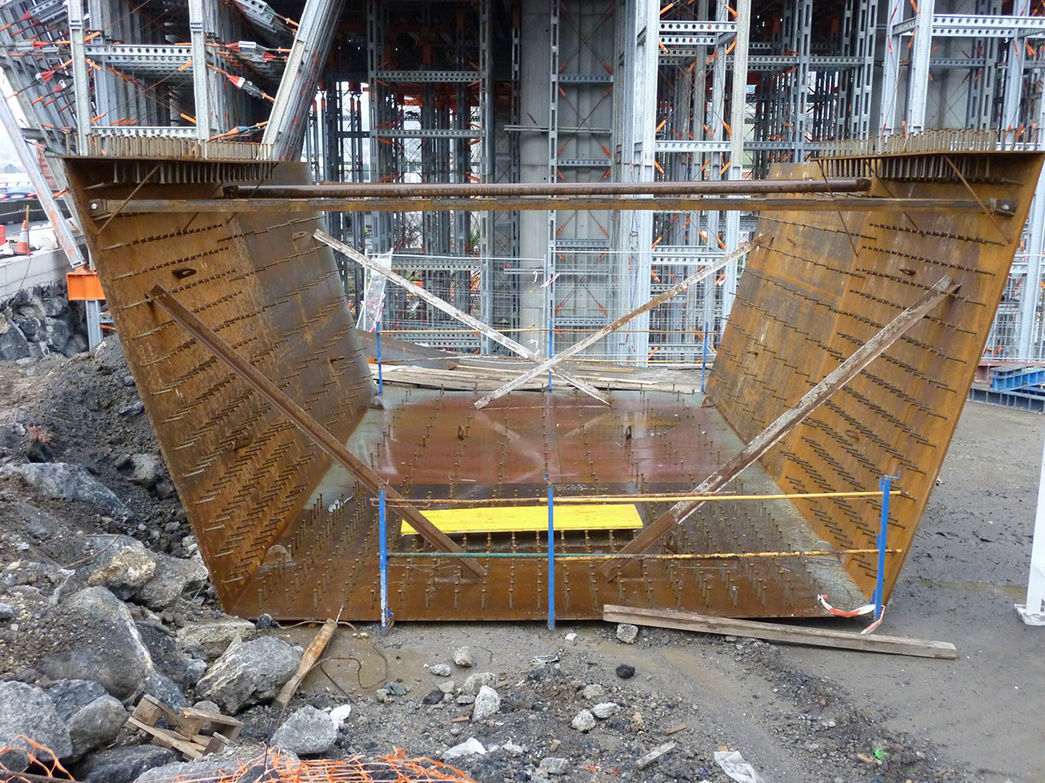
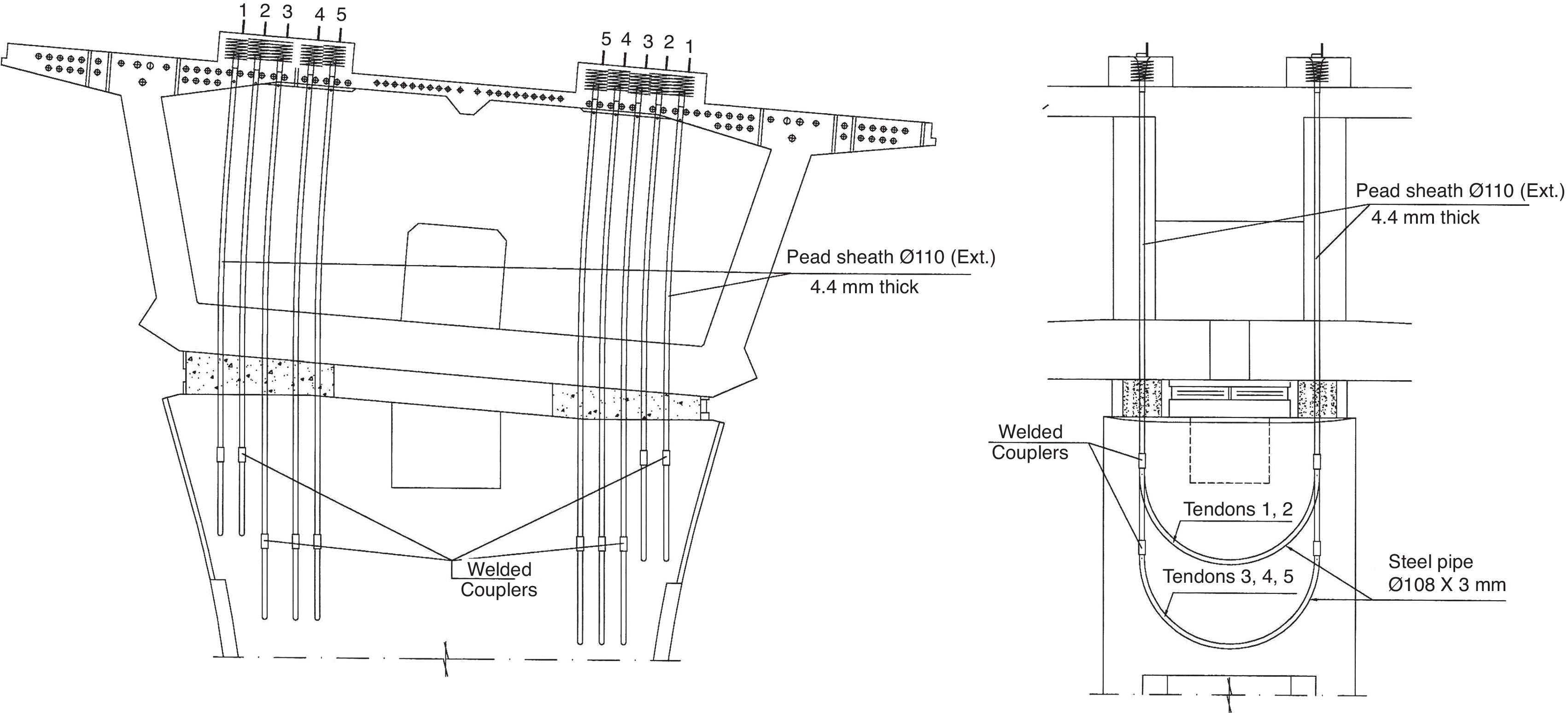
During the phases of balanced cantilever and in order to ensure stability of the structure, the deck was provisionally anchored to the pier head. This consisted of some concrete blocks joined using prestressed tendons that ensured the stability of the cantilever (Fig. 27). In order to obtain an adequate safety factor at ultimate limit state, the fixing tendons were injected and the concrete blocks were reinforced. In order not to condition the size of the pier, in the last segments, a maximum imbalance was allowed of half a segment during concreting.

Provisional fixing was by means of a classic scheme of leaving some curved steel pipes in the pier capital. Once the Segment Zero was finished, the tying tendons were lined up from the top part of the deck. This scheme prevents leaving any tendons of a similar height at the edge of the deck, anchored into the capital of the piers. Their stability during construction of Segment Zero is problematic.
Once the core of the deck reached a stable configuration, the blocks and tendons were cut using diamond thread. Because cutting the provisional fixing happens once the deck is stable, that is to say, without allowing time to elapse in which the phenomena of shrinkage and creep occurs, the moment of the said fixing is limited. Due to this and thanks to the reinforced blocks, cutting took place easily, without any abruptness or appearance of any small local damage. This operation was undertaken without the help of any jacks or sand boxes.
We should highlight that, at this stage, the vertical reaction does not reach even half the maximum value for which the bearings are designed. Therefore, transferring the vertical reaction of the block to the bearing takes place without any problem.
7.2Approach viaduct piersIn the approach branches, due to their curvature on the ground and limited space available, the piers are solid circular ones measuring 2.10m in diameter, with 4 grooves that make them look slender (Fig. 28).
7.3Transition area piers
The transition area rests on pier 0 of the main viaduct and on 3 almost rectangular prismatic piers with rounded walls that serve as a transition between the shapes of the piers in the main viaduct and those belonging to the approach branches. Their outer size is 2.20×4.40m (Fig. 29). All the piers of the approach spans and transition area have shallow foundations.
8Abutments
The start of the main deck rests on pier 0 where there is a road surface joint and the transition area. At the other end, it rests on abutment 2 (Fig. 30). This abutment is a large-sized loading platform that rests on ten 2.00m diameter piles, which must go through a newly formed 30m deep embankment, built using the material extracted from the SMB tunnels.

This embankment varies greatly in thickness in the transverse direction. This caused detailed analysis in the project phase to see how its transverse movements evolved over time. This analysis was carried out with and without considering the piles of the loading platform. From the calculation, the forecast for transverse movements up to 0.10m at the top of the landfill contiguous to the loading platform were calculated. For this reason the piles of abutment 2 are strongly reinforced. Furthermore, to a large extent to make the deck functioning independent from the landfill movements, very thick neoprene bearing pads were installed on abutment 2. Finally, inclinometers were left to measure the longitudinal and transverse movements of the embankment over the years. To date, these movements are within the foreseen figures.
In the approach viaduct, the abutments, as well as the walls of the link, have sloping walls with a few horizontal grooves and rounded corners like those of the main piers, thus giving the sensation of a formal unit (Fig. 31).
9Conclusions
The Trapagaran viaduct is characterized by its very wide deck. This involves a singular construction due to its dimensions and the shapes of the structural elements that give the observer a pleasing vision. The joint study of design and the construction process in the project phase has reverberated in completing the work within an extraordinarily short space of time.
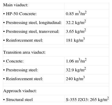
10Quantities| Main viaduct: | |
| • HP-50 Concrete: | 0.85m3/m2 |
| • Prestressing steel, longitudinal: | 32.2kg/m2 |
| • Prestressing steel, transversal: | 3.65kg/m2 |
| • Reinforcement steel: | 181kg/m3 |
| Transition area viaduct: | |
| • Concrete: | 1.06 m3/m2 |
| • Prestressing steel: | 32.9kg/m2 |
| • Reinforcement steel: | 240kg/m3 |
| Approach viaduct: | |
| • Structural steel | S-355 J2G3: 265kg/m2 |
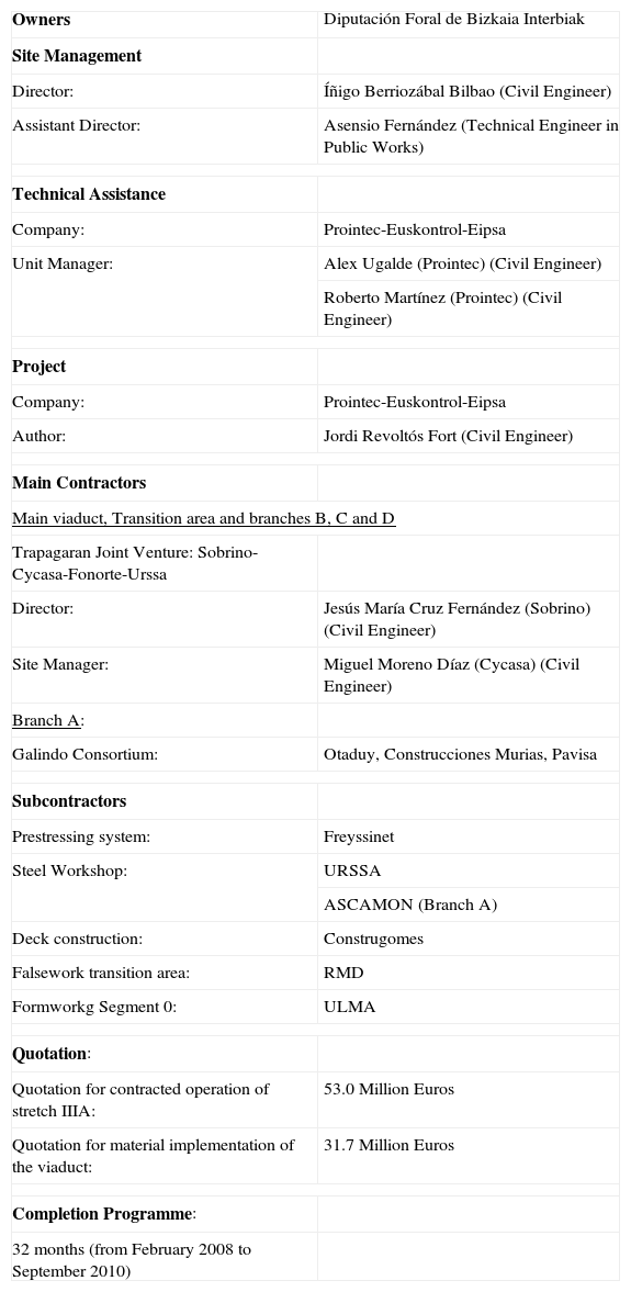
| Owners | Diputación Foral de Bizkaia Interbiak |
| Site Management | |
| Director: | Íñigo Berriozábal Bilbao (Civil Engineer) |
| Assistant Director: | Asensio Fernández (Technical Engineer in Public Works) |
| Technical Assistance | |
| Company: | Prointec-Euskontrol-Eipsa |
| Unit Manager: | Alex Ugalde (Prointec) (Civil Engineer) |
| Roberto Martínez (Prointec) (Civil Engineer) | |
| Project | |
| Company: | Prointec-Euskontrol-Eipsa |
| Author: | Jordi Revoltós Fort (Civil Engineer) |
| Main Contractors | |
| Main viaduct, Transition area and branches B, C and D | |
| Trapagaran Joint Venture: Sobrino-Cycasa-Fonorte-Urssa | |
| Director: | Jesús María Cruz Fernández (Sobrino) (Civil Engineer) |
| Site Manager: | Miguel Moreno Díaz (Cycasa) (Civil Engineer) |
| Branch A: | |
| Galindo Consortium: | Otaduy, Construcciones Murias, Pavisa |
| Subcontractors | |
| Prestressing system: | Freyssinet |
| Steel Workshop: | URSSA |
| ASCAMON (Branch A) | |
| Deck construction: | Construgomes |
| Falsework transition area: | RMD |
| Formworkg Segment 0: | ULMA |
| Quotation: | |
| Quotation for contracted operation of stretch IIIA: | 53.0 Million Euros |
| Quotation for material implementation of the viaduct: | 31.7 Million Euros |
| Completion Programme: | |
| 32 months (from February 2008 to September 2010) | |