


The manufacture of structured ceramic porous support knows an important boom since more than a decade with the development of new shaping techniques. Among the most promising ones, the freeze-casting also called Ice-Templating allows the fabrication of ceramic parts exhibiting high porosity (>50%) and vertically aligned and hierarchically organized pores. Such structures were firstly conceived for biomedical applications like bone substitute and tissue engineering, but the distinctive features of freeze-cast structures have attracted the attention of diverse scientific fields, especially in high temperature ceramic-based energy production systems. Indeed, technologies like (a) Solid Oxide Fuel Cell (SOFC) and Electrolyser Cell (SOEC), (b) gas separation (O2, H2) by asymmetric supported membranes based on mixed ionic and electronic conductors (MIEC) or hydrogen-permeable metals, and (c) Catalytic Membrane Reactor (CMR) systems present a porous component in their physical structure. This latest, presenting a tortuous pathway for gas access and as a consequence, a high transport limitation, is known to be a limiting component for the operation at high flow streams that would enable to reach industrial target.
The aim of this paper is to give an overview of the freeze-casting ceramic shaping method and to show how its implementation could be useful for several energy applications where key components comprise a porous scaffold. A detailed presentation of the freeze-casting process and of the characteristics of the resulting porous parts is firstly given. The characteristic of freeze-cast parts and the drawbacks of conventional porous scaffolds existing in energy applications are drawn in order to highlight the expected beneficial effect of this new shaping technique as possible substitute to the conventional ones. Finally, a review of the state of the art freeze-cast based energy applications developed up to now and expected to be promising is given to illustrate the large perspectives opened by the implementation of the freeze-casting of ceramics for energy fields. Here we suggest discussing about the feasibility of incorporate freeze-cast porous support in high temperature ceramic-based energy applications.
La fabricación de soportes cerámicos porosos a través de nuevas técnicas de conformado es clave en el desarrollo de nuevos dispositivos en el sector energético y de la ingeniería química. La técnica de freeze-casting (colado por congelación) permite obtener componentes cerámicos muy bien sinterizados, con muy alta porosidad y poros con formas concretas. Los poros se orientan de manera que las propiedades de transporte de fluidos a su través son óptimos con respecto a otros tipos de estructuras porosas más irregulares. Concretamente, en el sector de la energía los soportes porosos se utilizan en aplicaciones tales como pilas de combustibles de óxidos sólidos o electrolizadores, membranas para la separación de gases, típicamente O2 o H2, y reactores catalíticos de membrana. En este artículo se revisan de manera exhaustiva los desarrollos en estos campos utilizando freeze-casting para el conformado de cuerpos porosos cerámicos.
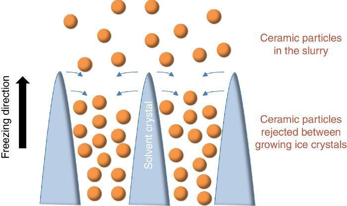
Since more than a decade, the growing interest for the development of ceramic parts with hierarchical porosity exhibiting high mechanical properties led the scientific community to focus on alternative shaping technique to substitute the conventional foaming technique ([1], [2]) and the use of pore former precursors. Indeed, they are quite simple to implement but the organization of the resulting porosity remains random in most of the cases. Even if new mathematical models for the representation of the tortuosity have been recently given ([3]), it remains very difficult to model such random microstructures. Among the emerging techniques, freeze-casting also known as ice-templating, is an attractive shaping method for the fabrication of highly porous and hierarchically organized ceramic structures. It consists of freezing generally by the bottom a ceramic slurry followed by the sublimation of the solvent by freeze-drying at both low pressure and temperature. The freezing of the ceramic slurry induces, in a repetitive pattern, the growing of vertical solvent crystals along the freezing direction and the associated rejection of ceramic particles between these crystals (Fig. 1). Finally, the as-obtained green body after solvent removal by freeze-drying is sintered for consolidation and the final freeze-cast sample exhibits hierarchically and vertically aligned porosity which is the replica of the original solvent crystals.

Fig. 1. Sketch of the growing of ice crystals during the freezing step and the associated distribution of ceramic particles rejected between the ice crystals.
Slurry formulation and porosity controlA basic ceramic slurry formulation for the freeze-casting comprises at least 3 components and its fine tuning enables to tailor pore size and shape, and overall porosity ([4], [5], [6], [7], [8]):
1. The first component is the ceramic powder. Its loading is usually in the range 10–50 vol% of the whole slurry ([9]). A lower value would be problematic for the mechanical integrity of the final structure with very thin ceramic walls while a higher value would not be favourable for the growing of solvent crystals and the subsequent formation of connected porosity due to the low solvent content in the slurry. Several physico-chemical characteristics of the powder will influence the slurry stability like the grain size, the acidity or the basicity, the distribution size or the specific surface area. Nevertheless, since the first pioneering shaping experiments using freeze-casting, it has been shown that almost all ceramic materials but also some metals can be used and shaped: alumina ([10]), yttria-stabilized zirconia YSZ (Y2O3 doped ZrO2) ([11]), titanium oxide ([12], [13]), glasses ([14], [15], [16]), but also composite materials like NiO-YSZ ([17]), LSCF (La0.6Sr0.4Co0.2Fe0.8O3−δ)–CGO (Gd2O3 doped CeO2) ([18]) and metals ([19]).
2. The second component of the slurry is the solvent. Up to now, literature details the use of three main solvents which are water ([7], [20]), camphene ([21], [22], [23], [24]) and tert-butyl alcohol ([25], [26], [27]), each one resulting in a different porosity shape. Water is the most common in the freeze-casting process due to the absence of chemical toxicity all along the process. The resulting porosity associated to the use of water as solvent presents a lamellar shape due to a vertical ice growing velocity much more important than the horizontal one. Camphene, which offers dendritic porosity ([28]), is also implemented as solvent since its solidification occurs in the temperature range 44–48 °C but its volatility can be struggling during the freezing step and could hinder achieving an homogeneous porous structure in all over the thickness ([29]). Finally, the tert-butyl alcohol, giving a porosity with prismatic shape ([25]), has also been used as solvent but in a less usual way.
3. The last component of the ceramic slurry corresponds to the additives and generally consist of: (i) a powder dispersant to ensure the stability and the viscosity of the slurry (to avoid sedimentation and gradient concentration during the freezing step), and (ii) a binder to provide a sufficient mechanical strength to the green body structure during the freeze drying step and thus avoid its collapse. Additives can also be present in the slurry as structuring agent ([30]). Indeed, as demonstrated by Deville et al., the presence of a zirconium acetate complex in an alumina slurry participates to the structuring of the porosity shape leading to a six-fold symmetry and a final honeycomb-like microstructure ([31], [32]). Before freezing, an additional step of de-airing in a vacuum desiccator can be realized to remove air bubble trapped into the slurry ([33]) while the use of few drops of an antifoaming agent can also be considered for a good homogeneity and the absence of air bubble during the freezing ([19]).
The versatility of the technique detailed above and the large variety of ceramic material selection and slurry composition from literature is detailed in Table 1.
Table 1. Overview of state of the art materials and slurry compositions used for freeze-casting process in energy applications.
| Material | Particle size d50 | Powder loading | Solvent | Binder | Dispersant/additives | Freezing conditions | Targeted application | Reference |
| Al2O3 | 1 μm | 20, 30, 40 vol% | Water | PVA 1 wt% | PA sodium 2 wt% | Copper rod | Various | [10] |
| Al2O3 | 0.37 μm | 45–62.5 vol% | Water | Acrylic emulsion 2 wt% | Ammonium PM 1.2 wt%/glycerol | Up to −35 °C | – | [20] |
| Al2O3 | 400 nm | – | Water | PVA | Ammonium PM 1 wt% + various additives | Metallic rod with temperature control | – | [5] |
| Ferritic stainless steels | 15–45 μm | 36–56 wt% | Water | Hydroxyethyl cellulose | Carboxymethylcellulose sodium salt | Between −40 °C and −80 °C | SOFC interconnector | [19] |
| LSCF/CGO/BSCF | 2 μm | 40–50 wt% | Water | PEG 1–4 wt% | PA 1–4 wt% | Copper rod | Permeation membrane | [53] |
| LSCF-CGO | – | 27 vol% | Water | – | Alon A-6114 | – | SOFC electrode | [18] |
| LSM-YSZ | 0.8–0.3 μm | 23 vol% | Water | PEG 5 wt% | Ammonium PM 1.6 wt% | Copper rod | SOFC cathode | [44] |
| TiO2 | 100–200 nm | 10–50 wt% | Water | PVA | Ammonium PA/PEG | Doctor Balde at −18 °C | – | [12] |
| YSZ | 1.26 μm | 15 vol% | TBA | PVB 0.5 wt% | Alkali solution | Copper rod | Thermal insulation | [11] |
| YSZ | 0.55 μm | 10–50 vol% | TBA | PVB | Ammonium PM | Solidification at RT over Al foil | SOFC electrodes, catalysts | [26] |
| Ca10(PO4)6(OH)2 (HAP) | 3 μm | 40–60 wt% | Camphene/water | CA | Dolapix/glycerol | RT/copper rod | Tissue engineering | [14] |
| Homemade Bioglass | <2 μm | 40–60 wt% | Camphene/water | CA | Dolapix/glycerol | RT/copper rod | Tissue engineering | [15] |
| Al2O3 | 0.4 μm | 20–49.5 wt% | Camphene | Amine derivative | – | Solidification at RT | Implantable bone scaffolds | [21] |
| NiO-YSZ | <100 nm | 20 vol% | Camphene | Oligomeric PE 3 wt% | – | Solidification at RT | SOFC electrode | [23] |
| PZT/PZN | 10–25 vol% | Camphene | Oligomeric PE 3 wt% | – | Solidification at RT | Low frequency hydrophones | [24] | |
| TiO2 | – | 14.87 wt% | Camphene | PS 0.56 wt% | Texaphor 3250 0.56 wt% | Solidification at RT | Photocatalysis | [13] |
TBA: tert-butyl alcohol; CA: carboxylic acid; PE: polyesther; PA: polyacrylate; PM: polymethacrylate; PEG: polyethylene glycol; PVA: polyvinyl alcohol; PVB: polyvinyl butyral; RT: room temperature.
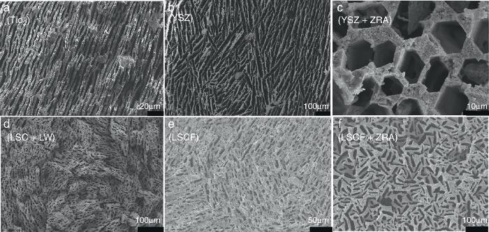
An interesting characteristic of the freeze-casting process is indeed its versatility through all the components of the ceramic slurry and the freezing conditions (temperature, velocity, direction). A set of microscopic images presenting freeze-cast structures obtained in our lab for different ceramic materials and slurry compositions is given in Fig. 2 as an example. We can see that 5 ceramics materials (TiO2, YSZ: 3 mol% Y2O3 doped ZrO2, LSC: La0.87Sr0.13CrO3, LW: LaWO12−δ LW and LSCF: La0.6Sr0.4Co0.2Fe0.8O3−δ) have been shaped. The porous organization, the porosity size and the thickness of the ceramic walls strongly vary from one to another. The influence of the presence of a structuring agent in the initial slurry is also depicted for the 3YSZ fluorite and the LSCF perovskite structures. For the 3YSZ material, we clearly note the honeycomb-like structure above mentioned while the combination of the LSCF powder and of the zirconium complex results in porosity with rectangular shape.

Fig. 2. Set of fracture cross-section FE-SEM images for freeze-cast structures obtained for different ceramic materials and slurry compositions: (a) TiO2, (b and c) 3 mol% Y2O3 doped ZrO2 (YSZ) without and with a zirconium acetate complex (ZRA) structuring agent respectively, (d) composite material La0.87Sr0.13CrO3 (LSC) – La5.5WO12−δ (LW) and (e and f) La0.6Sr0.4Co0.2Fe0.8O3−x (LSCF) without and with a zirconium acetate complex structuring agent respectively.
Finally the last degree of freedom available for the tailoring of the porosity is the control of the freezing velocity ([34]). Indeed, by modifying the velocity it is possible to tune the pore size. As a general rule, the slower the freezing velocity, the larger the solvent crystals and thus the porosity width after the freeze-drying step ([35]).
Originally, the first references relating the use of freeze-cast structure present the development of hydroxyapatite structure for biomedical applications such as bone substitute and tissue engineering ([15], [36], [37], [38]). Considering that the interest of the ceramic scientific community towards the freeze-casting really started about 10 years ago, the majority of the papers published up to now essentially focus on the elementary understanding of the technique and the effect of each parameters over the final porous structure. Nevertheless and due to the specific hierarchical microstructures offered by these freeze-cast structures, i.e. large aligned pores with high porosity generally >50%, a wide range of opportunities for several applications can be imagined, especially in the field of the energy production ([39]).
Porous supports for energy applicationsSustainable energy production represents today a great challenge because of the large CO2 emission from industrial production resulting in the global warming and the climatic change. Among the different technologies considered as promising for an improved and greener energy production, we have decided to focus on the Solid Oxide Fuel Cell (SOFC) and Electrolyser Cell (SOEC), the O2/H2 separation by mixed ionic and electronic asymmetric ceramic membrane (MIEC) and the Catalytic Membrane Reactor (CMR). These systems present similarities in their configuration and operation like the operating temperature (in the range 400–1000 °C), the materials involved in their fabrication (mixed oxides, perovskites and metals) and finally the presence of a porous component in their physical structure. In the case of MIEC membrane and CMR the porous support is generally made of only one material exhibiting both ionic and electronic conductivity while for a SOFC, electrodes are made of two different materials presenting each one a specific conductivity (Fig. 3). For chemical compatibility and thermal expansion purposes, the porous support is generally made of the same material than the dense layer one.
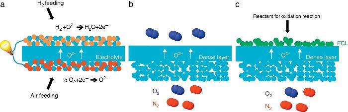
Fig. 3. Sketches of 3 high temperature ceramic-based energy production applications including a porous component in their structure: (a) Solid Oxide Fuel Cell, (b) oxygen permeation MIEC membrane and (c) oxygen-based Catalytic Membrane Reactor (CMR). FCL stands for Functional Catalytic Layer.
RequirementsFor these technologies, the porous element has two different functions.
1. The first one is to maintain the mechanical integrity of the membrane assembly made of porous support, dense thin-film and catalytic interfaces. Focusing on the Wagner's law ruling the gas permeation in a MIEC membrane when the bulk diffusion is the main controlling step, i.e. at high temperature generally >700 °C (for lower temperatures, the surface exchange may become the rate-limiting process and the Wagner's law is no longer applicable), it is necessary to minimize the dense top layer thickness to increase the permeate flux ([40]). Conventional ceramic coating techniques like screen-printing or dip-coating allow the elaboration of micrometric-scale layer while advanced coating techniques like radiofrequency (RF) sputtering or chemical vapour deposition (CVD) permit to reach the sub-micrometre scale. Such thin layer cannot be handled without a support which has to be porous for the reason previously detailed. It is interesting to note that this function is also sought in the case of an anode-supported SOFC where the electrolyte is the thinnest element of the stack and where one porous electrode (typically the anode) gives the mechanical stability to the cell assembly.
2. The second function of the porous support is physico-chemical and relies on providing (i) a high mixed electronic and ionic conductivity and (ii) a high density of Triple Phase Boundary (TPB) where ion, electron and gas can meet for reaction. Indeed, due to the low reaction site density on the interface porous support/dense layer, it is worthy that the porous support exhibits a high density of TPB where the gaseous oxygen (in the case of O2 separation) and the electronic and ionic conductive phases are gathered. In this case only, the gaseous oxygen can be dissociated in molecular O2− species and then transported to the dense layer where the permeation occurs.
As detailed above, porous supports are today mainly prepared by conventional ceramic techniques and by using polymeric or graphite pore former precursors. It results generally in a non-optimized, random and tortuous pathway for gas diffusion and as a consequence, leads to high gas transport limitations in the porous media; it is also call concentration polarization. This process is caused by the depletion of the active molecules (e.g. O2 or H2) and the accumulation of retentate molecules (e.g. N2 or CO2) in the pore system that precludes the diffusion of the active molecules towards the top thin separation layer. This situation strongly reduces the overall permeation. It appears that the porous support limitations are major in the overall process (specifically in the case of MIEC/Pd membranes and CMR) and partly hinder to reach the targeted requirement for industrial applications. The need of improving the porous structure and to fabricate hierarchical scaffolds ([41]) is real and the most interesting option lies in the implementation of the freeze-casting process. Indeed, as detailed in the introduction section, freeze-cast structures exhibit a high porosity coupled with large vertically aligned pores, both characteristics sought for boosting gas transport through the porous support of energy production systems like SOFC, high-temperature gas-separation membranes and CMR.
Experimental techniqueThe fabrication of freeze-cast part is generally realized by the same way whatever the solvent or the slurry composition. The slurry is casted in a Teflon® mould plugged to a metallic (copper, aluminium etc.) rod. The latest is immerged in liquid nitrogen or an ethanol-dry ice bath (or casted at ambient temperature in the case of camphene as solvent) and the cooling down of the slurry takes place to a velocity depending on the thermal conductivity of the metal used for the rod. After removal from the mould, the sample is freeze-dried at both low temperature and pressure during several hours to remove the solvent crystals. The final sintering step of the green body gives a handling densified sample with vertically aligned and hierarchical porosity. As detailed above, it is also possible to tailor the porosity size by controlling the freezing velocity ([42]). It implies the use of a liquid nitrogen circuit coupled with temperature controller for the progressive freezing of the slurry. Nevertheless, due to the complexity of such setup, the first option is the most common in literature.
Freeze-casting and energy applications: state of the art and outlookUp to now, literature related to freeze-casting and high temperature ceramic-based energy applications remains limited. Nevertheless, some research groups have started to conceive how the freeze-casting technique could be implemented to these processes. This section aims to emphasize on the results present in literature up to now.
Solid Oxide Fuel CellsThe first reference to SOFC and freeze-casting in literature is attributed to Moon et al. ([18]). Using camphene as solvent, they prepared a freeze-cast composite of the La0.6Sr0.4Co0.2Fe0.8O3−x (LSCF) and Ce0.9Gd0.1O1.95 (CGO) prototypical oxide-ion conducting powders exhibiting a porosity of 42.1% after sintering at 1350 °C. Then, they coated a 30 μm thick CGO dense layer on the surface of the freeze-cast composite facing the metallic rod during the freezing step. Indeed, during the first instant of freezing, it exists a transient state where the growing of solvent crystals has not reach yet its steady state thus giving smaller and less ordered crystals. The resulting porosity of such layer is smaller and the subsequent coating of functional layers becomes easier due to the lower mean pore diameter. Finally, a half-cell cathode/electrolyte with a highly porous and organized cathode microstructure for SOFC system was obtained. The same group also published the development of a tubular freeze-cast NiO-YSZ composite as anode fuel cell ([17]). By modifying the original setup configuration to a tubular metallic mould immerged in liquid nitrogen, they developed a 2 mm thick NiO-YSZ composite freeze-cast porous support with radially aligned pores. The further coating of a dense YSZ layer gave a half-cell with tubular configuration. Despite a promising organized porous architecture, both references do not detail the slurry composition, the powder dispersion and the homogeneity of the metal and of the ceramic in all over the electrode volume. This characteristic is very important especially for the anode microstructure in order to minimize the possible mechanical constraint created during the reduction reaction of NiO to metallic Ni before the SOFC operation. Gannon et al. also manufactured a NiO-8YSZ/YSZ half-cell using freeze-casting and specific physical vapour deposition (PVD) techniques to fabricate the anode and to coat a <1 μm dense electrolyte respectively ([43]). An interesting preliminary work has been performed by Wei et al. They used the freeze-casting technique to fabricate hierarchical and porous ferritic stainless steel support as possible interconnector for fuel cell gas supplying ([19]). The resulting structure exhibits porous channels of about 50 μm width for a total porosity ranging 21–38% according to the initial metal loading. Finally, a three-layer structure consisting of a porous LSM-YSZ cathode, a dense YSZ electrolyte and a standard NiO/8YSZ cermet anode was deposited onto the green metallic tapes by screen printing. Nevertheless, the final cell has not been evaluated in realistic conditions and no more data became available. More recently, Lichtner et al. published a study dealing with the preparation of a freeze-cast cathode for SOFC system ([44]). The work emphasizes the essential good control of the dispersion for the two components LSM and YSZ powders in order to optimize the percolation of both phases and the number of TPB.
All these results are very promising since they demonstrate the feasibility of Solid Oxide Fuel Cell anode, cathode and interconnector fabrication by the freeze-casting technique. By controlling both the slurry preparation and composition and the freeze-casting process, it is possible to obtain a homogeneous well-sintered composite or a metallic microstructure with hierarchical porous organization at large scale, both being key points for boosting gas transport. Nevertheless and despite these interesting results, literature does not detail more than the fabrication step and no evaluation in realistic conditions has been reported yet. Thus, it remains difficult to quantify the beneficial effect of freeze-casting towards the fuel cell technology.
Gas separation membranePermeation membrane for gas separation detailed Fig. 2 is today one of the most interesting substitute to existing systems for O2/H2 production thanks to its low energy consumption and the high purity of the produced gas. Here again, very few reports for the implementation of the freeze-casting are available in literature.
Involved materialsPerovskite ABO3−δ compounds are one of the most studied membrane materials for oxygen production with easy cation substitutions enabling the material to be tuned and thus the intrinsic properties, like ionic and electronic conductivities, catalytic activity and chemical stability towards CO2 atmosphere, to be improved. Among the most studied perovskite materials, we can cite La0.6Sr0.4Co0.2Fe0.8O3−δ (LSCF) and Ba0.5Sr0.5Co0.8Fe0.2O3−δ (BSCF), presenting the highest oxygen permeation in the temperature range from 600 °C to 1000 °C. Specifically, LSCF is a promising candidate since it combines a competitive O2 separation rate with acceptable thermo-chemical stability in realistic gas environments for different applications such as oxy-fuel based power plants and IGCC (Integrated Gasification Combined Cycle). Another class of materials matching the targeted characteristic is the cer-cer (for ceramic-ceramic) family ([45], [46]). These composite materials are composed of two ceramic structures exhibiting each one a specific conductivity (ionic or electronic) and can be synthesized by a one step process bringing small grain size, improved morphology, homogeneity of both phases for a complete percolation of both conductive phases and promising stability under CO2 ([47]) and also SO2 ([48]) atmosphere. This option is interesting since it may overcome the trade-off existing with MIEC materials. Indeed, the cations substitutions in MIEC structure can result in a final loss of chemical stability under the harsh industrial conditions of the technologies detailed above.
Concerning the proton-conducting membranes, the most common materials are based on the SrCeO3−δ and BaCeO3−δ perovskite structures. They usually present a very high protonic conductivity but are instable in presence of SO2 and CO2. Another family of proton-conducting materials is based on zirconate perovskite, exhibiting high protonic conductivity but requiring generally a very high sintering temperature (generally >1700 °C) leading to issues during the shaping process and a decrease of the sought conductivity. As possible substitute to these materials, the tungstate (Ln6WO12) family is widely studied since few years and present the advantage to be stable under CO2 and SO2 atmosphere ([49], [50], [51], [52]). These materials find application in (1) electrochemical systems based on proton-conducting electrolytes, such as ceramic proton-conducting fuel cells/electrolysers, galvanic H2 separators and H2 sensors, and (2) semi-permeable H2 membranes and associated membrane reactors.
Results from the state of the artThe main results come from the Instituto de Tecnología Química (ITQ) and deal with O2 transport membranes. Recently, we developed two innovative asymmetric freeze-cast ceramic MIEC membranes for oxygen production. These two reports presenting the implementation of freeze-casting for high temperature gas permeation membrane and its evaluation under realistic conditions initiated the activity in this area.
The first one was fabricated with the LSCF perovskite material (from Oerlikon-Metco) known to exhibit a high mixed ionic and electronic conductivity and a relatively good stability in presence of CO2. The elaborated freeze-cast support exhibits 60% of porosity with large and aligned pores with averaged sizes between 5 μm and 20 μm. A 30 μm-thick dense top-layer of the same material was screen-printed over the freeze-cast support and the whole membrane was evaluated for oxygen permeation (Fig. 4). This freeze-cast membrane exhibits unprecedented oxygen flux with a maximum value of 6.8 mL min−1 cm−2 at 1000 °C under air. The values are markedly above the results achieved so far with conventional preparation techniques, i.e. with tape-casting (Fig. 5a). The interest of the freeze-casting technique for the manufacture of porous support has been widely pointed out in this study with the evaluation of the pressure drop for three gases through the freeze-cast porous support and its systematic comparison with a porous support elaborated by conventional techniques. As detailed in Fig. 5b, the pressure drop through a freeze-cast support is always lower than the pressure drop through a conventional support. It remains very moderated even with an inlet flux of 400 mL min−1 with a value of only 0.53 bar mm−1 while it is of about 8 bar mm−1 at the same inlet flux for a conventional support exhibiting a random porosity ([53]).
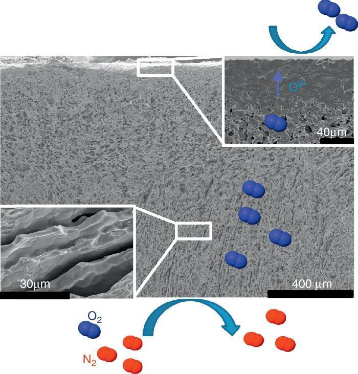
Fig. 4. FE-SEM image of the LSCF freeze-cast asymmetric membrane and related O2 separation from air.
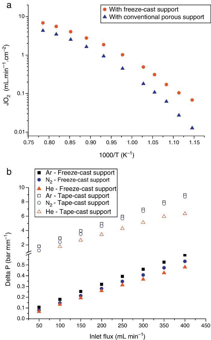
Fig. 5. (a) Evolution of the oxygen permeation flux as a function of temperature for an asymmetric freeze-cast membrane and for an asymmetric membrane presenting a support elaborated by tape-casting with pore former precursor [40] . Both membranes are made of the LSCF perovskite materials and the dense top layers have a similar thickness of 30 μm; (b) normalized pressure drop ΔP across two LSCF porous supports (empty symbols: support prepared by freeze-casting, filled symbols: support of the asymmetric membrane developed in [40] ) as a function of the Ar, He and N2 flow rate and at 900 °C.
Such freeze-cast asymmetric membrane has also been catalytically activated by screen-printing a 30 μm thick LSCF porous layer over the dense top layer of an asymmetric freeze-cast LSCF membrane and evaluated for oxygen permeation. Membrane activation leads to a noticeable improvement of the oxygen permeation flux (JO2) in the low-temperature region (<700 °C), at which catalytic gas exchange is the most limiting process. An enhancement of 54% in JO2 is obtained (JO2 = 0.17 mL min−1 cm−2) in air at 600 °C thanks to the addition of the LSCF catalytic porous layer, whereas the maximum oxygen permeation is reached when pure oxygen is fed to the membrane at 1000 °C with a high value of 16.3 mL min−1 cm−2. The most appealing effect of the catalytic layer is its protective feature under oxycombustion conditions, that is, under a CO2-rich atmosphere at high temperature ([54]).
Recently, an optimized composite materials NiFe2O4/Ce0.8Tb0.2O2−δ has been developed and presents promising oxygen permeation permeance and unprecedented chemical stability in CO2 and SO2 ([48]). After a full study of chemical reactivity with the LSCF perovskite, this material has been implemented as dense top-layer over a LSCF freeze-cast porous support. The final asymmetric membrane revealed promising oxygen permeation fluxes with peak values of 4.8 and 12 mL min−1 cm−2 at 1000 °C in argon using air and pure oxygen as feeds, respectively. The stability under CO2 was also evaluated and showed a very low degradation with time ([55]).
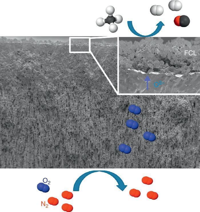
Catalytic Membrane ReactorA CMR is a gas permeation membrane activated with a functionalized porous catalytic layer (FCL) allowing a heterogeneous catalytic reaction like suggested in Fig. 6 with the methane partial oxidation. The coupling of a reaction consuming the permeated O2 increases very strongly the permeation flux, since the driving forces is the different of natural logarithms of the O2 partial pressures as postulated by Wagner's law. In this situation, the gas transport in the porous support can become limiting and the use of freeze-cast porous structures can alleviate the diffusion limitations. The surface functionalization of the membrane on the permeate side increases the number of active sites for the targeted catalytic reaction. This is typically done by applying porous catalytic coatings with thickness below 100 μm.

Fig. 6. FE-SEM image of an all LSCF Catalytic Membrane Reactor operating the methane partial oxidation for syngas synthesis (CH4 + ½O2 → 2H2 + CO). FCL stands for Functional Catalytic Layer.
The integration of ceramic CMR operating at high temperature in power plants and energy-intensive industries makes it possible the energy-efficient separation of CO2. In the case of partial oxidation reactions ([39], [56]) in petrochemical industry, the use of CMR enables the operation at high yields and minimizes downstream (separation and recycling) costs, since high hydrocarbon concentration can be fed without surpassing flammability/exposition limits, in contrast to conventional reactors, which are strongly limited to small hydrocarbon concentration in feed. Up to now and due to the lack of literature, it cannot be found any publication of freeze-cast-based CMR.
Water desalinationAmong the different membrane applications in energy-intensive industries and where freeze-cast porous scaffolds could be positively implemented, we can additionally cite liquid filtration and treatment, and specifically we will focus on water desalination. Indeed, this process does not take place at high temperature and under gaseous atmosphere but the porous characteristics of the freeze-cast scaffolds appear to be quite attractive focusing on the last progress dealing with carbon nanotubes (CNTs) for water treatment.
Salt removal from seawater is one of the biggest challenges of today's world for giving access to pure water to everybody especially in underdeveloped countries. Nowadays, reverse osmosis is the process implemented at the industrial level for water desalination. The selective barrier of such membrane is generally made of an aromatic polyamide with pore smaller than 0.6 nm ([57]). Industrially developed in the 70s, the process has reached maturity and studies have recently confirmed that industrial plants operate at the thermodynamic restrictions limits ([58]). The emergence of new technologies and in particular of nano technologies opens a wide range of opportunities and alternatives to existing membrane processes. In the last decade, the development and focus on CNTs ([59], [60], [61], [62]) for salt rejection from seawater has shown that its implementation could allow to compete with polymeric-based membranes and to decrease the consumed energy and carbon footprint of industrial plant by operating at higher flows. For this, it will be necessary to get a porous structure to support these CNTs and presenting a (i) minimal tortuous pathway for water diffusion and (ii) the possibility to activate its surface walls with the deposition of CNTs by Chemical Vapour Deposition (CVD) ([61], [63]). In this optic, the freeze-cast porous scaffolds appear like a valuable option and deserve to be studied. A schematic representation of CNTs deposited into a freeze-cast porous scaffold is given in Fig. 7.
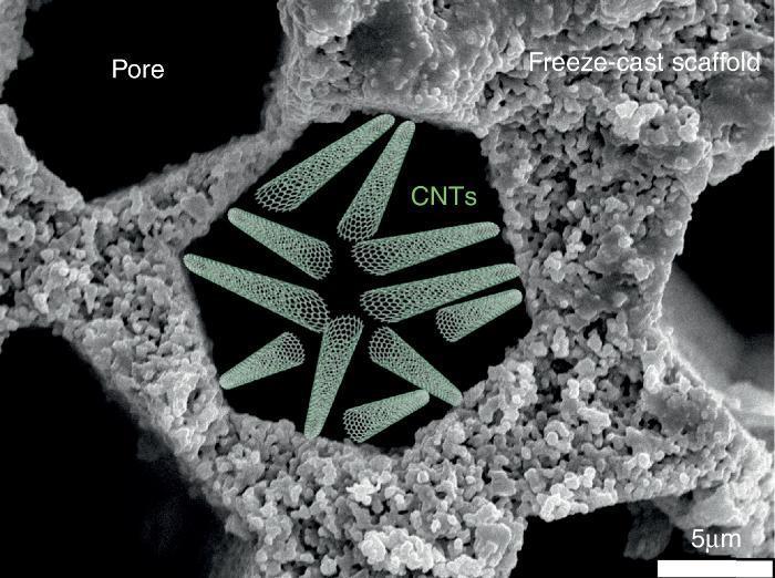
Fig. 7. Schematic representation of CNTs deposited into the porosity of a freeze-cast scaffold for water desalination application.
ConclusionsThis paper presents a survey of the freeze-casting shaping technique highlighting its versatility and great potential in the field of high temperature ceramic-based energy applications such as Solid Oxide Fuel Cells, gas separation membranes and advanced Catalytic Membrane Reactors. The introduction section has shown that the hierarchical and vertically aligned porosity structures obtained by freeze-casting present all the characteristics for boosting gas transport and to substitute randomly organized porous support which hinder to reach industrial targets. Few reports of existing freeze-cast energy applications are available in literature but the first published results have shown the feasibility of incorporate freeze-cast porous structures as SOFC and MIEC membrane component. Water desalination has also been pointed out as a possible application even if the complete lack of literature data does not allow to rule about it. The authors think that freeze-casting is a very young technique although the first results are very promising and open a wide range of perspective for different applications. Time and experimental dedication is worthy and will lead to a major improvement of existing ceramic-based energy technologies.
Acknowledgements
Financial support by the Spanish Ministry for Science and Innovation (ENE2011-24761 and SEV-2012-0267 grants) and by the EU through FP7 GREEN-CC Project (Grant Agreement Number: 608524) is gratefully acknowledged.
Received 7 January 2016
Accepted 12 February 2016
Corresponding author. jmserra@itq.upv.es
