

Cohesive zone models (CZM) are a powerful tool for the design of bonded structures, but they require careful estimation of the cohesive laws for reliable results. This work experimentally evaluates by the J-integral/direct method the tensile and shear CZM laws of three adhesives with distinct ductility. Additionally, by the direct method, the precise shape of the cohesive law in tension and shear of the adhesives is defined. The double-cantilever beam (DCB) and end-notched flexure (ENF) specimens were considered to obtain the tensile and shear CZM laws of the adhesives, respectively. After obtaining the tensile and shear CZM laws, triangular, exponential and trapezoidal CZM laws were built to reproduce their behaviour. Validation of these CZM laws was undertaken with a mixed-mode geometry (double-lap joint) considering the same three adhesives and varying overlap lengths (LO). The strength prediction by this technique revealed accurate predictions for a given CZM law shape, depending on the adhesive ductility, although all CZM law shapes were moderately accurate.
Currently, significant efforts are being made in the design of aircraft and aeronautical applications to reduce weight and improve reliability. Thus, adhesive bonding techniques have been largely employed, which also enables the combined use of steel with lighter materials such as aluminium or high strength composites. This, in turn, promotes less fuel consumption and reduction in the CO2 emissions to the atmosphere, consequently bringing a major environment-related advantage [1,2]. Other advantages over mechanical joints are the increase in productivity regarding costs and fabrication times, excellent insulation, superior damping, noise reduction and improved aesthetics [3]. Pethrick [4] recently presented a comprehensive review regarding the adhesives’ selection for structural applications. Limitations of bonded joints include the requirement and correct choice of surface treatment to the bonding surfaces, and sensitivity to temperature and humidity [5].
There is a countless number of joint configurations addressed in the literature, although the most common are single-lap, double-lap and scarf joints [6]. The availability of accurate and straight-forward predictive methods is thus mandatory for the safe design of bonded joints.
Although several techniques have been proposed for many decades, beginning with the theoretical analysis of Volkersen [7], the continuum mechanics criteria coupled to a finite element analysis (FEA), linear elastic fracture mechanics (LEFM) or the CZM. CZM been refined ever since were initially proposed some decades ago, to become nowadays a very powerful technique for damage growth and strength prediction of structures, including the analysis of wood failure [8], composite delaminations [9,10] and bonded joint analysis [11,12], for which this technique is particularly suited [13].
While CZM is a powerful technique to predict the strength of bonded joints, some premises must be accounted for to ensure reliable results: the adhesive should be characterized under identical geometrical conditions in which the resulting laws will be used in the simulations, and the stipulated CZM law shape should be consistent with the adhesive's behaviour [14].
Different techniques are nowadays available for the definition of the cohesive parameters (GIC, GIIC, tn0 and ts0), such as the property identification technique, the direct method and the inverse method. The direct method, which is the purpose of this work, gives the precise shape of the CZM laws of a specific material or interface, since these are estimated from the experimental data of fracture tests such as the DCB or ENF [15]. This is done by differentiation of the tensile strain energy release rate, GI, for tension, or the shear strain energy release rate, GII, for shear, with respect to the relative opening of the crack (δn for tension or δs for shear). Nonetheless, it is usual to convert the obtained shape to an approximated parameterized shape for introduction in the FEA software. For an accurate measurement of the required parameters such as δn or δs, physical sensors [16] or image correlation methods [17,18] can be used. The validity of the direct approach can be checked by numerically replicating the tensile or shear fracture tests with identical dimensions and with the experimentally obtained CZM laws as input for the adhesive layer's behaviour, followed by comparing the obtained P–δ curves with the original ones from the experiments [18]. However, complete validation of the CZM laws should include testing the pure mode CZM laws in a mixed-mode geometry, although to the authors’ knowledge such works are not available in the literature, being these works limited to pure-mode verifications.
This work experimentally evaluates by the J-integral/direct method the tensile and shear CZM laws of three adhesives with distinct ductility. Additionally, by the direct method, the precise shape of the cohesive law in tension and shear of the adhesives is defined. The DCB and ENF specimens were considered to obtain the tensile and shear CZM laws of the adhesives, respectively. After obtaining the tensile and shear CZM laws, triangular, exponential and trapezoidal CZM laws were built to reproduce their behaviour. Validation of these CZM laws was undertaken with a mixed-mode geometry (double-lap joint) considering the same three adhesives and varying LO values.
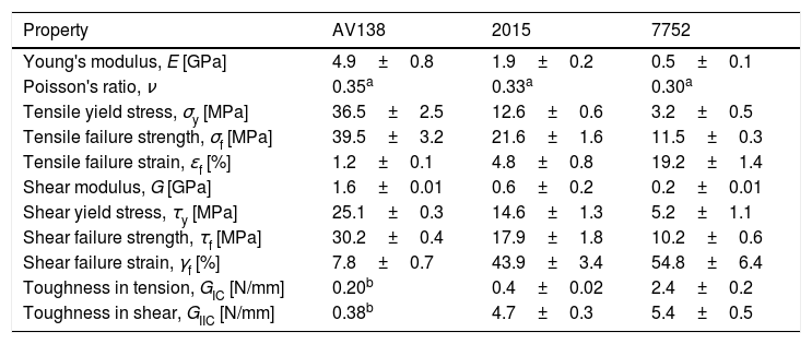
2Experimental work2.1MaterialsFor the DCB, ENF and double-lap specimens, the high strength and ductile aluminium alloy AA6082 T651 was chosen for the adherends. The tensile mechanical properties of this material were obtained in the work of Campilho et al. [12]. The experimental testing programme included three structural adhesives: the brittle epoxy Araldite® AV138, the ductile epoxy Araldite® 2015 and the ductile polyurethane Sikaforce® 7752. In this manner, different material behaviours are tested. These adhesives were previously characterized regarding the mechanical and toughness properties [12,19,20]. Bulk specimens were tested in a servo-hydraulic machine to obtain Young's modulus (E), σy, σf and ɛf. The DCB test was selected to obtain GIC and the ENF test was used for GIIC. The collected data of the adhesives is summarized in Table 1.
Properties of the adhesives Araldite® AV138, Araldite® 2015 and Sikaforce® 7752 [12,19,20].
| Property | AV138 | 2015 | 7752 |
|---|---|---|---|
| Young's modulus, E [GPa] | 4.9±0.8 | 1.9±0.2 | 0.5±0.1 |
| Poisson's ratio, ν | 0.35a | 0.33a | 0.30a |
| Tensile yield stress, σy [MPa] | 36.5±2.5 | 12.6±0.6 | 3.2±0.5 |
| Tensile failure strength, σf [MPa] | 39.5±3.2 | 21.6±1.6 | 11.5±0.3 |
| Tensile failure strain, ɛf [%] | 1.2±0.1 | 4.8±0.8 | 19.2±1.4 |
| Shear modulus, G [GPa] | 1.6±0.01 | 0.6±0.2 | 0.2±0.01 |
| Shear yield stress, τy [MPa] | 25.1±0.3 | 14.6±1.3 | 5.2±1.1 |
| Shear failure strength, τf [MPa] | 30.2±0.4 | 17.9±1.8 | 10.2±0.6 |
| Shear failure strain, γf [%] | 7.8±0.7 | 43.9±3.4 | 54.8±6.4 |
| Toughness in tension, GIC [N/mm] | 0.20b | 0.4±0.02 | 2.4±0.2 |
| Toughness in shear, GIIC [N/mm] | 0.38b | 4.7±0.3 | 5.4±0.5 |
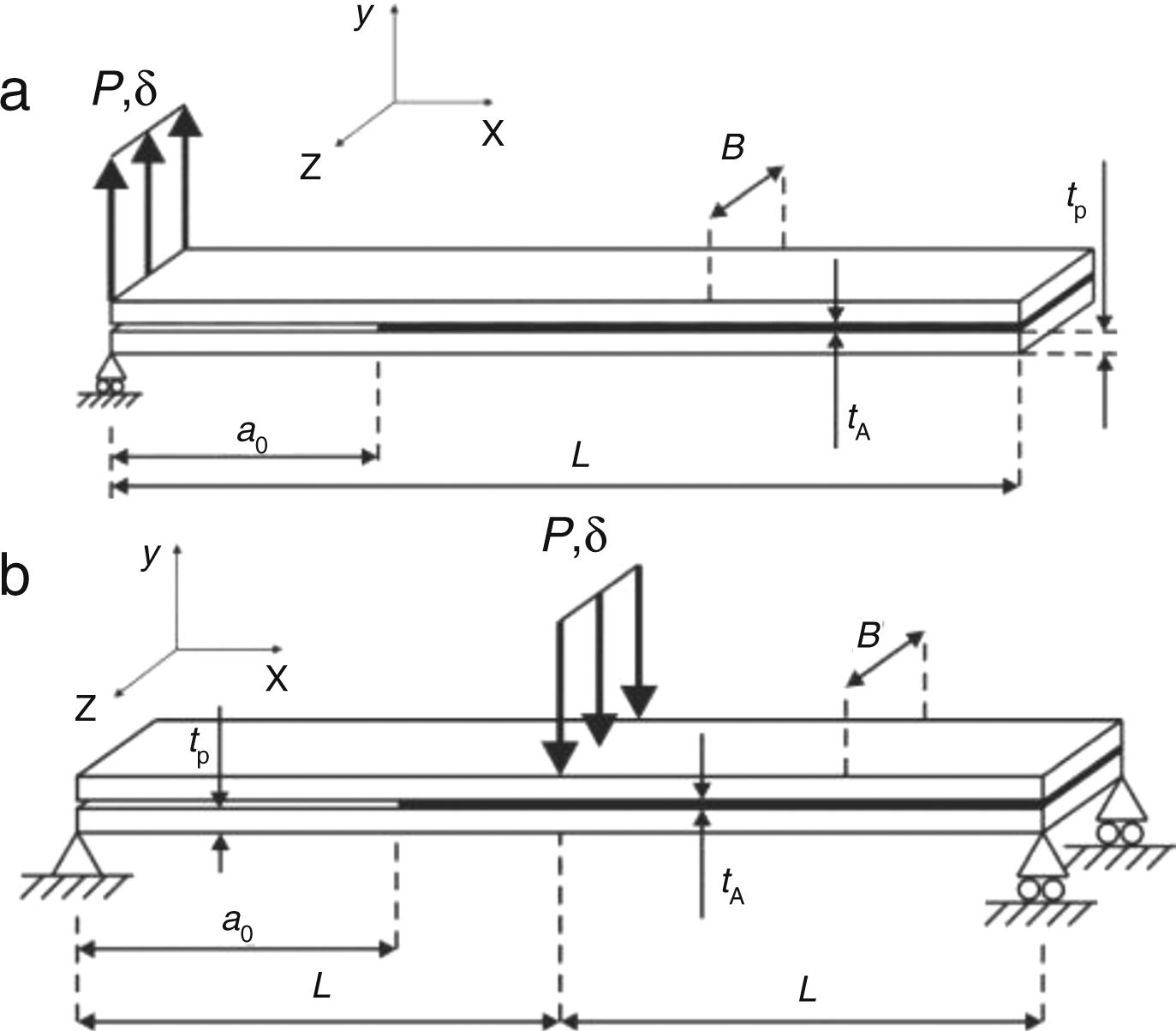
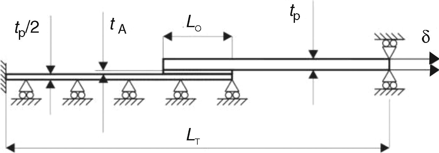
Fig. 1 shows the geometry and characteristic dimensions of the DCB (a) and ENF specimens (b). The chosen values for the dimensions are: total length L=140mm (DCB) or mid-span L=100mm (ENF), initial crack length a0≈50mm, adherend thickness tP=3mm, tA=0.2mm and width B=25mm. Fig. 2 describes the double-lap joints’ geometry for validation of the obtained CZM laws, whose dimensions were the following: length between grips LT=170mm, tP=3mm, tA=0.2mm, LO=12.5, 25, 37.5 and 50mm and B=25mm (not represented in the figure).
 and ENF (b) specimens for fracture characterization of thin adhesive bonds.")

All joint configurations were fabricated and tested at room temperature. Joint tests were carried out in a Shimadzu AG-X 100 electro-mechanical testing machine with a 100kN load cell. To apply the optical methods used in the DCB and ENF tests, images were recorded by an 18 MPixel digital camera with no zoom and fixed focal distance to approximately 100mm, which enabled obtaining the values of a, δn, δs and adherends rotation at the specimen's loading point, θo, this last parameter required in the DCB tests for application of the J-integral.
2.3Direct method for cohesive law estimationBased on the fundamental expression for J[21], it is possible to derive an expression for GI (Eq. (1)) applied to the DCB specimen from the concept of energetic force and also the beam theory, as follows [22]
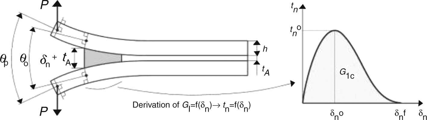
where Pu represents the applied load per unit width at the adherends’ edges and Ex is the adherends’ value of E in the longitudinal direction. A schematic representation of δn, θo and θp, required by this method, is given in Fig. 3.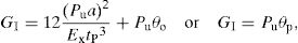

In this figure, δn0 is the relative displacement at tn0, and δnf is the tensile failure displacement. The tn(δn) or tensile CZM law is obtained by differentiation of Eq. (1) with respect to δn. More details about this technique applied to the DCB specimen can be found in Ref. [23]. A developed algorithm to measure θo and δn was used [24], based on digital image correlation and tracking reference points in the scales that follow crack growth during the test.
An identical procedure, i.e., based on the direct method, was used to evaluate GIIC and shear CZM law by the ENF test [22,23], involving the concurrent measurement of the J-integral and δs. The GII expression (Eq. (2)) for the ENF specimen gives [25]
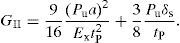
The ts–δs curve (or shear CZM law) can then be assessed by differentiation of the GII–δs curve. Full details regarding the description of the direct method applied to the ENF specimen, as well as the algorithm to estimate δs in every picture of a test, can be found in the work of Leitão et al. [26].
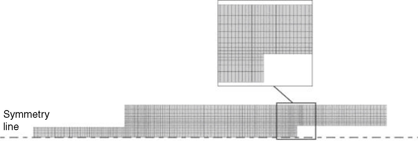
3Numerical analysis3.1Conditions of the numerical analysisGeometrically non-linear analyses were considered for the double-lap joint models. The adherends were modelled as elasto-plastic continuum bodies and the adhesive was fully represented by a single layer of cohesive elements, i.e., by the continuum CZM approach [19]. The models are two-dimensional, considering CPE4 plane-strain elements of Abaqus®. Apart from this, horizontal symmetry was applied to the double-lap joints. Fig. 4 shows a representative mesh for the CZM strength prediction analysis for a double-lap joint with LO=25mm. The FEA mesh included edge grading horizontally from the overlap inner portion towards the overlap edges, and vertically towards the adhesive layer, to increase the simulation speed, although keeping acceptable results. The joints were clamped at one edge and a vertical restraint and tensile displacement was applied at the opposite edge [27].
3.2CZM implementation in the FEA analysis.")
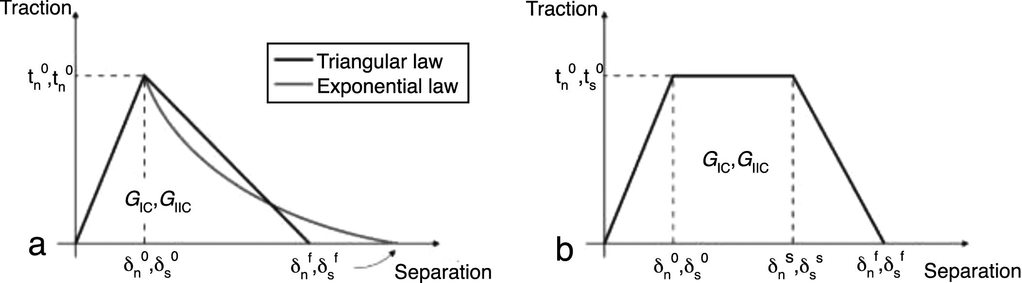
CZM are typically founded on a relationship between tn/ts and δn/δs that connects homologous nodes of the cohesive elements, to simulate the elastic behaviour up to tn0 (tension) or ts0 (shear) and subsequent material degradation up to final failure [28]. In this work, the triangular, trapezoidal and linear-exponential shapes were evaluated to model the tensile and shear behaviour of the adhesive layer. Fig. 5 schematically represents these three CZM shapes with the associated nomenclature for both tensile and shear loadings (δs0 the relative displacement at ts0, δsf is the shear failure displacement, and δns and δss are the tensile and shear stress softening onset displacements of the trapezoidal CZM law, respectively). The definition of δnf and δsf is carried out by making GI=GIC for tension or GII=GIIC for shear [28].

Due to the unavailability in Abaqus® of mode coupling for the trapezoidal and exponential CZM laws, uncoupled loading modes were considered in all CZM simulations. This is supported by the findings of a previous work [19], in which it was found for composite single-lap joints that the results between mode-coupled and uncoupled predictions are virtually identical.
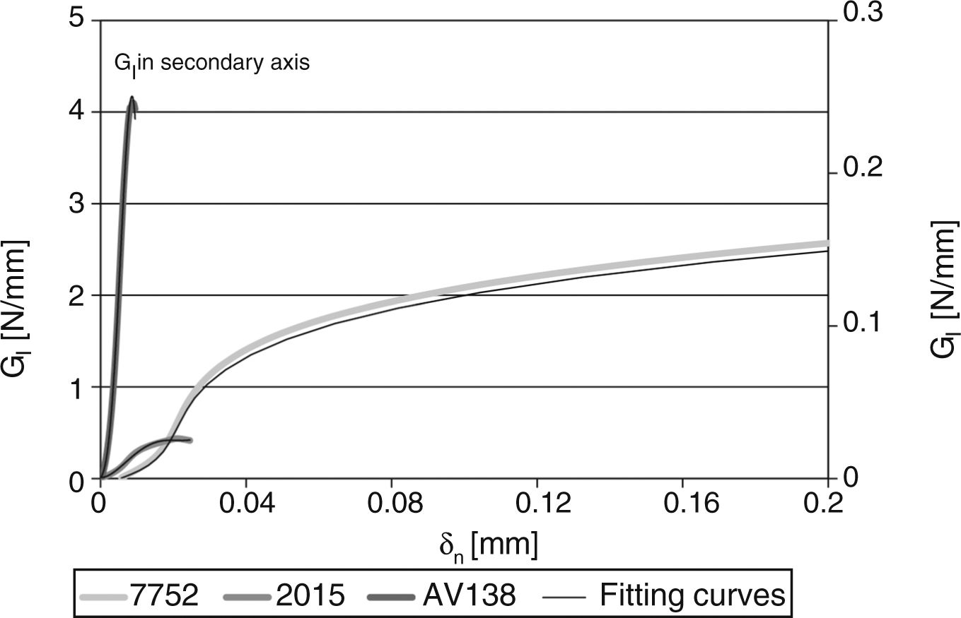
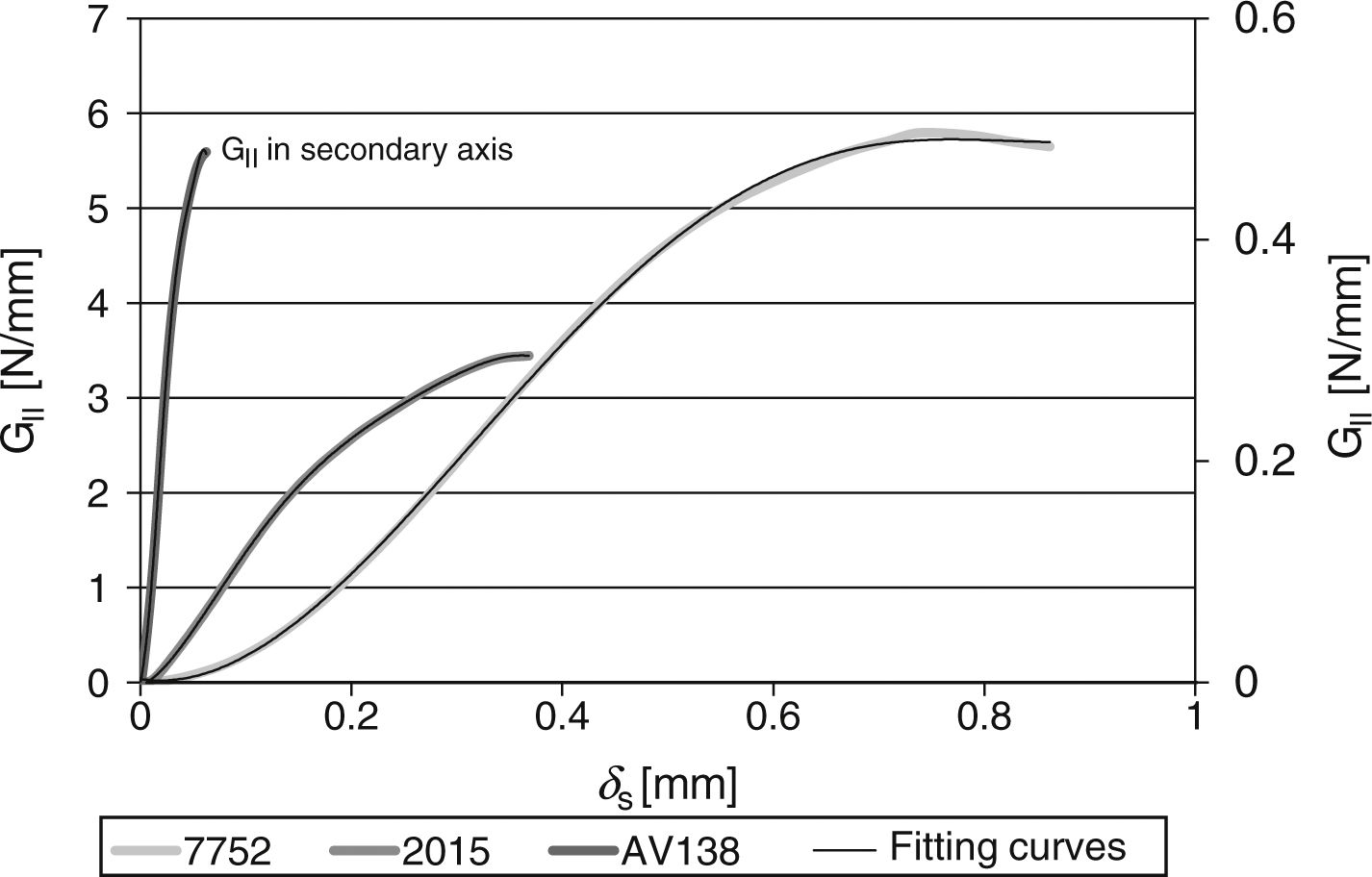
4Results4.1GIC and GIIC evaluation by the fracture testsAll DCB and ENF specimens revealed a cohesive failure of the adhesive layer. The GI–δn and GII–δs curves were estimated from the direct method described in Section 2.3 using Eqs. (1) and (2), respectively. Figs. 6 and 7 show typical curves for the three adhesives and the DCB and ENF tests respectively, overlapped by polynomial approximation curves to apply the differentiation procedure leading to the definition of the respective CZM laws.


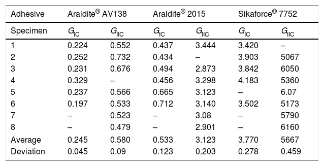
In agreement with previous works [9], three different stages can be identified in the GI–δn and GII–δs curves: (1) slow increase of GI/GII with δn/δs, (2) steady increase of GI/GII and (3) the curve tends to a steady-state value of GI/GII. The different behaviour between the three adhesives is clearly visible. The curves for each adhesive highly differ in terms of GIC/GIIC measurement and corresponding value of δn/δs, which corresponds to failure in the CZM law. GIC and GIIC are found by the steady-state values of GIC and GIIC in the respective curve and are attained at crack initiation [16]. Table 2 reviews the GIC and GIIC values obtained by the J-integral for the three adhesives.
Values of GIC and GIIC [N/mm] for the three adhesives obtained by J-Integral technique [29–31].
| Adhesive | Araldite® AV138 | Araldite® 2015 | Sikaforce® 7752 | |||
|---|---|---|---|---|---|---|
| Specimen | GIC | GIIC | GIC | GIIC | GIC | GIIC |
| 1 | 0.224 | 0.552 | 0.437 | 3.444 | 3.420 | – |
| 2 | 0.252 | 0.732 | 0.434 | – | 3.903 | 5067 |
| 3 | 0.231 | 0.676 | 0.494 | 2.873 | 3.842 | 6050 |
| 4 | 0.329 | – | 0.456 | 3.298 | 4.183 | 5360 |
| 5 | 0.237 | 0.566 | 0.665 | 3.123 | – | 6.07 |
| 6 | 0.197 | 0.533 | 0.712 | 3.140 | 3.502 | 5173 |
| 7 | – | 0.523 | – | 3.08 | – | 5790 |
| 8 | – | 0.479 | – | 2.901 | – | 6160 |
| Average | 0.245 | 0.580 | 0.533 | 3.123 | 3.770 | 5667 |
| Deviation | 0.045 | 0.09 | 0.123 | 0.203 | 0.278 | 0.459 |
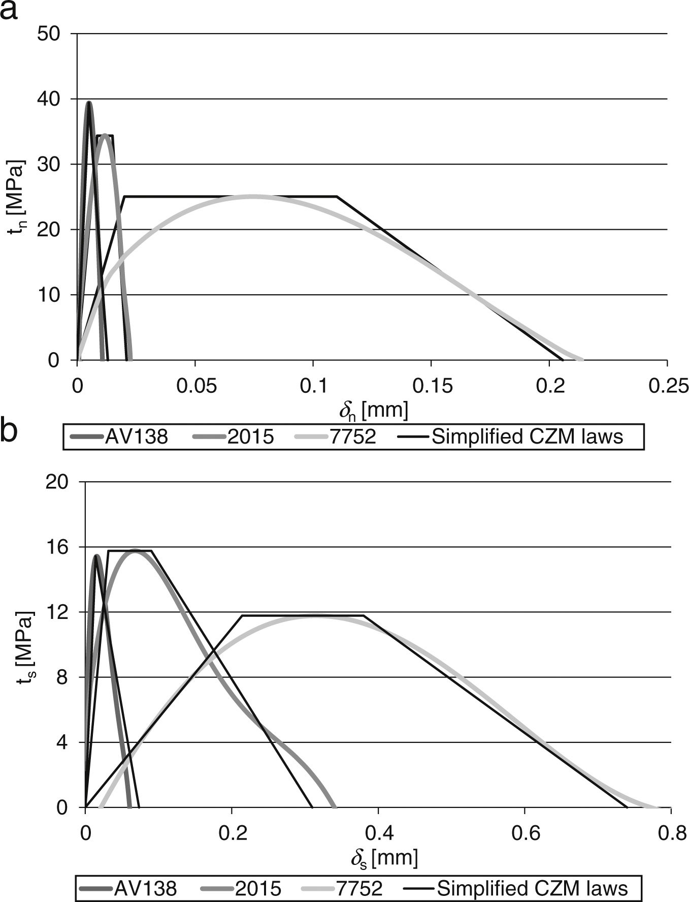
Fig. 8 presents a comparison between representative tn–δn (a) and ts–δs (b) curves for each of the adhesives (corresponding to the GI–δn and GII–δs curves of Figs. 6 and 7, respectively). Both tensile and shear CZM laws show that the Araldite® AV138 is best fit by a triangular CZM law because of its brittle behaviour, whilst the Araldite® 2015 and Sikaforce® 7752 are modelled with trapezoidal CZM laws which, in this case, provide the best approximation on account of the plasticization endured after the initial elastic part of the curves. The different behaviour of these three adhesives under tension is consistent with the properties of the adhesives reported in Table 1, namely ɛf and GIC (tensile CZM laws) and the shear failure strain, ɛf, and GIIC (shear CZM laws). The deviation in the CZM parameters showed a reduced scatter between CZM laws of the same adhesive.
4.2Strength prediction and ts–δs (b) curves for each of the adhesives.")
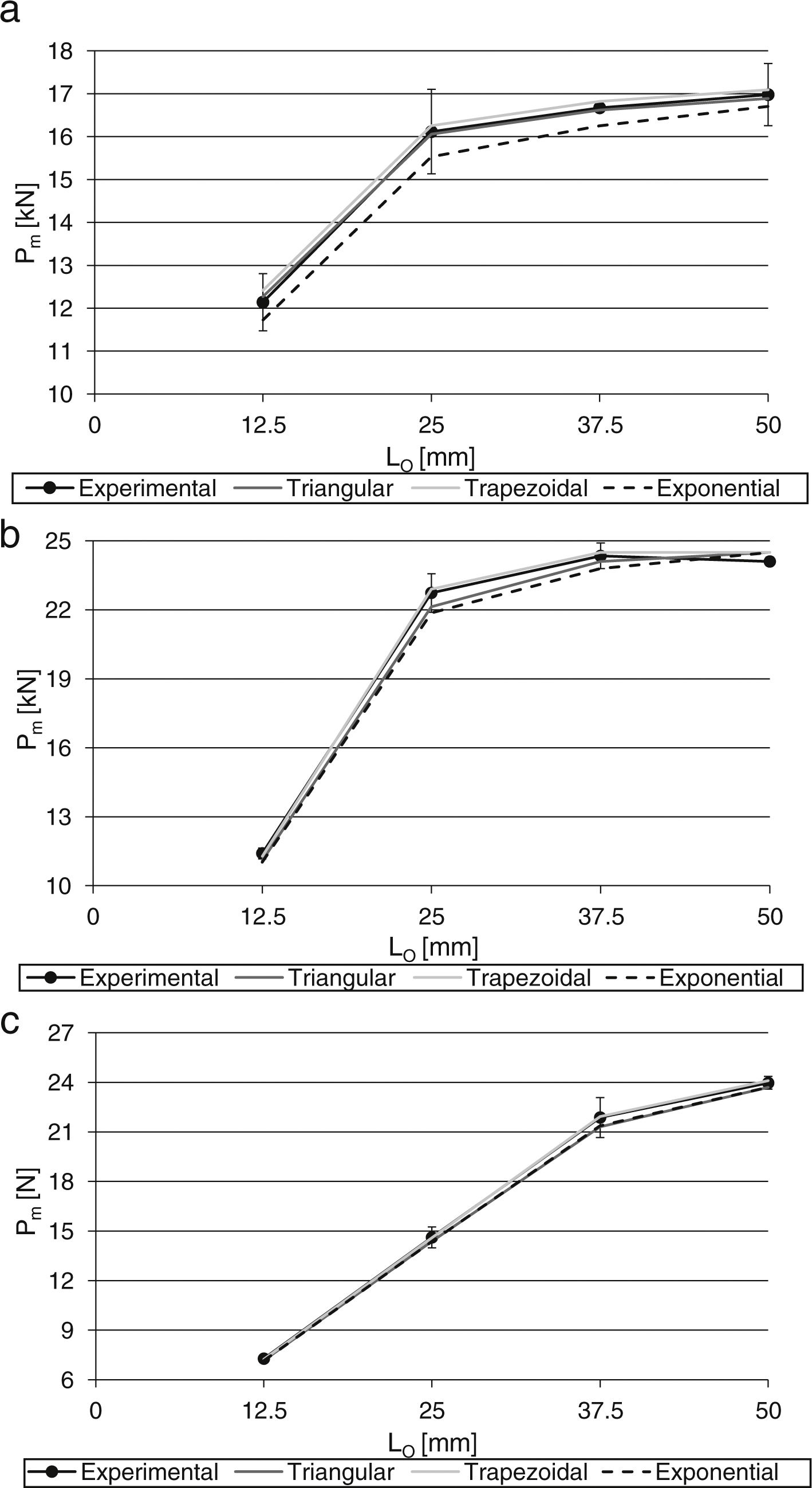
The average values of tensile and shear CZM parameters were used to build triangular, trapezoidal and linear-exponential tensile and shear CZM laws for each of the three adhesives. These laws were subsequently input in numerical simulations of double-lap joints respecting the principles depicted in Section 3.1 as a validation of the obtained CZM laws by the J-integral/direct method. Fig. 9 compares the experimental and numerical maximum load (Pm) values as function of LO for the three CZM laws and the adhesives Araldite® AV138 (a), Araldite® 2015 (b) and Sikaforce® 7752.
, Araldite® 2015 (b) and Sikaforce® 7752 (c).")
The comparison between the experiments and CZM predictions by the different law types showed that, for the joints bonded with the Araldite® AV138, the best results are obtained by the triangular CZM law, followed by the trapezoidal CZM law, while the linear-exponential CZM law clearly under estimates Pm. These results are justified by the brittleness of the adhesive, which was attested by the properties depicted in Table 1 and tensile and shear CZM laws represented in Fig. 8. The average absolute error (considering the four LO values) is 0.56% for the triangular CZM law, 1.17% for the trapezoidal CZM law and 2.79% for the linear-exponential CZM law. The largest % errors always occur for LO=12.5mm, disregarding the CZM law type. Differently to this adhesive, for the joints bonded with the Araldite® 2015, the best predictions were attained with the trapezoidal CZM law, which is consistent with the moderate degree of ductility of this adhesive. The triangular and especially the linear-exponential CZM laws under predict the experiments. The average deviations of absolute values, considering all LO values, are 2.00% (triangular law), 1.03% (trapezoidal law) and 2.76% (linear-exponential law). For this particular adhesive, it was found that, from LO=37.5mm, Pm is ruled by the adherends’ yielding/tensile net failure rather than the adhesive.
Because of the high ductility of the Sikaforce® 7752, for the joints bonded with this adhesive the trapezoidal CZM law gives the best approximation, while the triangular and linear-exponential CZM laws present identical under predictions. The average % deviations of absolute values of each adhesive are 1.73% (triangular law), 0.36% (trapezoidal law) and 1.73% (linear-exponential law). For LO=50mm, Pm is governed by the adherends’ yielding or tensile net failure. Globally, for the tested geometrical conditions, no significant errors would be made by using an improper CZM law, i.e., a CZM law that is not the best fit to the tensile and shear CZM laws of the respective adhesive obtained by the direct method. However, this is the result of two factors: (1) the range of LO values used is this work is relatively limited and (2) for all adhesives, tensile adherend failure or at least adherends plasticization affected the Pm results such that, for the higher Pm values, the joints’ failure was no longer ruled by the adhesive but by the adherend's yielding. In fact, in a previous work [19] considering triangular and trapezoidal CZM shapes to model single-lap joints with LO values up to 80mm revealed that higher LO values in joints with non-yielding composite adherends can give differences of over 10% compared to the experiments if the CZM law does not closely follow the adhesive's behaviour. Thus, depending on the required accuracy for the results, the choice of the correct CZM law type may be of importance.
5ConclusionsThe main objective of this work was the assessment of different CZM shapes in predicting the behaviour of a mixed-mode joint geometry bonded with adhesives of distinct ductility, after estimating the tensile and shear CZM laws of the adhesives by the direct method. The DCB and ENF specimens were considered to obtain the tensile and shear CZM laws of the adhesives, respectively. The obtained CZM laws were highly consistent for each loading/adhesive combination. In both loading modes, the Araldite® AV138 was best modelled by a triangular CZM law due to its brittleness, while the ductile Araldite® 2015 and Sikaforce® 7752 showed a better fit with trapezoidal CZM laws. Validation of these CZM laws was undertaken with a mixed-mode geometry (double-lap joint) considering the same three adhesives and varying LO values. Previous to the analysis, the double-lap joints’ strength revealed to be highly dependent on the adhesive type. Actually, the Araldite® AV138 showed a similar Pm value to the Araldite® 2015 for LO=12.5mm, but it was unable to increase Pm with LO by a significant amount on account of being very brittle (oppositely to the Araldite® 2015). The joints bonded with the Sikaforce® 7752 showed a much smaller Pm value for LO=12.5mm because of the smaller strengths, but the ductility of this adhesive enabled to increase Pm with LO in a practically linear relation. All Pm–LO curves for the three adhesives were affected by the inner adherend's failure or at least plasticization for the higher LO values. Regarding the Pm comparison between the experiments and numerical predictions, the deviations were small for all CZM laws, although the best results closely followed the previously mentioned agreement regarding the experimental and approximated CZM laws. Thus, for the tested geometrical conditions, no significant errors would be made by using an improper CZM law. However, it should be noted that, depending on the geometry of the joints and adherends’ behaviour, the error of using a non-consistent CZM law shape to the behaviour of the adhesive to be simulated can result in non-negligible deviations to the real joints’ behaviour.
