


The growing dependence of critical civil infrastructure on global positioning system (GPS) makes GPS interference not only a safety threat, but also a matter of national security. The research done in this paper is initiated by the need to diminish this trouble on GPS based positioning. The suggested compensation technique assumes that the presence of a spoofing signal is immediately determined. The position residuals of the last authentic and new fake signals are passed to the wavelet transform (WT). We utilized WT for de-noising. Afterwards, position deviations due to an attack can be extracted and then the estimated position of the received signal will be corrected. As a primary step, the proposed algorithm has been implemented in a stationary software GPS receiver to prove the concept of the idea. The performance of the technique is validated using several laboratory and measurement data sets. Interference mitigation having tolerance of 3% and average of 99.5% is yielded on laboratory data set and complete compensation is achieved on measurement data set. The test results show that the proposed technique supremely gain strength the reliability of civil stationary GPS receiver against interference.
From cars to commercial airplanes, global positioning system (GPS) technology is ubiquitous and it can be hacked or “spoofed”. In spoofing attack, the counterfeit GPS signal is generated to manipulate a target receiver's position or time. Spoofing attack can be classified into three main groups: simplistic, intermediate and sophisticated attacks. Simplistic spoofer attaches a power amplifier and an antenna to a GPS signal simulator and then radiates the radio frequency (RF) signal toward the target receiver. The second group synchronizes its counterfeit signals with the authentic GPS signals. Therefore, the fake signals can more-easily be masqueraded as genuine. Sophisticated attacks contain several receiver-spoofers utilizing shared reference oscillator and a communication link adjusted to the target antenna. Simplistic spoofer can produce GPS signal, but cannot make them to be aligned with the current broadcast GPS signals. However, if the adversary can transmit signals with the power higher than that of the legitimate signal, misleading commercial receivers would be possible. The third category is the most effective method of the spoofing generation. Whatever, physical limitations for placing the attacker antenna toward the victim receiver have made their implementation so hard and impossible in some cases because of target receiver's motion (Baziar, Moazedi, & Mosavi, 2015). Although, the receiver-spoofer can be formed small enough to place indistinctly near the antenna of the victim receiver. It seems that the applicable version of spoofing will be the intermediate since it is accessible and implantable in software-defined-receiver (SDR). Therefore, we will oppose an intermediate spoofing in which the main GPS signal is re-sent to the target receiver after some precise delay.
During the past decade, several anti-spoofing algorithms have been developed and tested (Lee, Kwon, An, & Shim, 2015). Of course, spoof recognition has been more outstanding. A desirable criterion for countering algorithms is that it can be added to civil GPS receivers easily. Through many suggested spoof-recognition methods, a real-time detection algorithm in GPS receiver is accessible. However, the necessity of developing a new spoof mitigation algorithm that can be implemented simply in civil GPS receiver is clearly observable.
In this paper, we have introduced a novel technique for GPS data processing based on wavelet transform (WT), which assumes that a real-time spoof detection method stands on SDR. In order to implement simply in the receiver, the suggested algorithm has been implemented in the position solution of the GPS receiver. In our anti-spoofing approach, we also performed a de-noising procedure based stationary WT (SWT) over position residuals.
The rest of this paper organized as follows. Section 2 reviews previous anti-forgery approaches with their advantages and disadvantages. Section 3 proffers a novel spoof compensation algorithm; after a short description of main idea, we will introduce WT and its application principles in GPS signal processing. This section then presents a detailed explanation of the implemented algorithm. Section 4 discusses both laboratory and measurement spoofing data sets and test results taken from interference reduction. A precise comparison between previous and suggested techniques is coming up at the end of the section. Finally, Section 5 states the conclusion.
2Previously proposed interference reduction methodsMost of the attempts in anti-spoofing field dedicate to detect and few of them relate to spoof mitigate. Since our subject is spoof reduction, we do not study recognizing methods but it is presented a review of spoof reduction techniques with a fault-finding look on them.
The proposed method in Lin, Haibin, and Naitong (2007) constantly investigates the internal and external information and estimate the authentic signal. This receiver has two operation modes. In the normal mode, the receiver relies on the collected information and in the alert mode, it compares the predicted values against to the obtained position-velocity-time solutions. The location prediction in this system is implemented by Kalman filtering or inertial sensors. This algorithm is not suitable for long-time spoofs because the estimation error grows during the attack.
In Mosavi, Nasrpooya, and Moazedi (2016), the adaptive filter is used for estimating the parameters of authentic and forgery signals. Interference elimination is performed by subtracting the estimated conflict effects from the measured correlation function.
Due to practical limitations, simplistic and intermediate attacks transform several counterfeit signals from single-source, while the legacy signals are transmitted from different satellites and directions. Thus, spatial processing can be used to estimate the three-dimensional effects of the received signals (Magiera & Katulski, 2015) by antenna array. There are three different ways to implement the antenna array. First, multi-antenna receiver utilizes an array processing technique to shape its beam. After denotation of counterfeit signal direction, it steers a null toward the attacker source and so negates harmful influence. The two-antenna array detects the different incident signals from different antennas by cross-correlation. Moreover, by moving a handheld receiver with a single-antenna, a form of a synthetic array can be generated (Broumandan, Jafarnia-Jahromi, & Lachapelle, 2015). This technique is reliable, but takes more computational and hardware complexity so it is not implantable in common civil receivers. The main idea in vector-based (VB) tracking technique is combining both navigation solution and the signal tracking burdens in order to increase the robustness of GPS receivers against to the interference (Jafarnia-Jahromi, Lin, Broumandan, Nielsen, & Lachapelle, 2012). It increases the complexity of hardware and processing.
Another technique, called receiver autonomous integrity monitoring (RAIM), uses the redundant information to detect and mitigate integrity threat at the navigation and position solution level (Ledvina, Bencze, Galusha, & Miller, 2010). This method detects damaged pseudo-ranges or carrier Doppler shift frequency and excludes the measurement errors from navigation solution via statistical hypothesis testing. It is effective only in cases where only one or two spoofed measurements are present among several authentic pseudo-ranges. They are also quite effective for the less sophisticated attacks. It seems that the GPS system will not provide cost-effective security by using these methods. Therefore, the necessity of introducing a more accessible technique with higher accuracy is clearly observable.
3Wavelet based anti-spoofing approachThis paper presents an anti-deception technique which is directly executable after uncovering the attack. The considered signal parameters include the position solution. We used difference in the last authentic and current fake signals to extract spoof error. Recent researches reveal that WT is an efficient tool for the isolation and separation of signals from noise (Xuan & Rizos, 1997). By passing position residual to the statistic WT at the first step and de-noising in the next step, position deviations due to the attack can be extracted. Then, the estimated position of the received signal has been corrected. The following subsection offers some insight into the mathematical basis of WT and its application in GPS signal processing to better perceive the suggested method.
3.1Wavelet transform utilization in GPS signal processingWT is a specific signal processing tool to extract information from signals. A standard WT can be expressed as:
where * denotes complex conjugation, w is the wavelet function, s is the dilation factor, τ is the translation, ψs,τ(t) is mother wavelet (Xuan & Rizos, 1997). After applying initial signals to a WT, yielded wavelet coefficients can be manipulated in many ways to achieve certain results such as filtering, de-noising, sub-band coding, compressing, feature detecting, etc. (Xiang, Liao, Zeng, & Wang, 2013). Firstly, Collin and Warnant (1995) introduced the WT for the purpose of GPS cycle slip correction. Ogaja, Rizos, Wang, and Brownjohn (2001) introduced the WT to analyze the GPS results in a structural monitoring application. In Ref. (Azarbad & Mosavi, 2014) after applying SWT to the double difference residuals, the multipath error is extracted by de-noising and it used to correct position errors. De-noising of signals using the WT is our subject in this article. Much information about signals in many applications usually lies in a few numbers of wavelet coefficients that possess larger amplitude in comparison with other coefficients. An appropriate threshold can put out noise of a signal. Mainly, it is not possible to completely filter out the noise without harming the initial signal. However, the performance can be optimized by selecting the proper WT.3.2Wavelet transform selection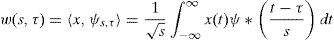
The continuous WT (CWT) was developed as an alternative approach to the short time Fourier transform (STFT) to overcome the resolution problem. It is apparent that analytical equations and integrals can perform neither the STFT, nor the CWT. Therefore, it is necessary to discretize the transforms. This conducts WT to discrete wavelets. In many practical applications such as GPS, the signal of interest is sampled. A simple solution is implementing the wavelet filter banks for construction of the multi-resolution time-frequency plane. This expansion is called discrete WT (DWT) which provides sufficient information both for analysis and synthesis of the original signal. Through a significant reduction in the computation time, it is considerably easier to implement when compared to the CWT (Xuan & Rizos, 1997). SWT is similar to DWT except that the signal is never sub-sampled and instead, the filters are up sampled at each level of decomposition. By using SWT instead of standard WT, created coefficients are more than sufficient to reconstruct the original signal. This causes additional choices to be selected the required coefficients and then the performance of the algorithm can be improved by selecting better ones among all existing coefficients (Jumah, 2013). Indeed, it can stretch, shift and process each scale signal precisely and improves the ability of WT signal processing. As a result, this paper attempts to use SWT for de-noising process.
Another aspect in WT selection is its dimension (Harvala, 2012). Complex WT is a complex-valued extension to the standard DWT. It is a two-dimensional WT which provides multi-resolution, sparse representation, and useful characterization of the structure of a signal (Jalobeanu, Kingsbury, & Zerubia, 2001). In our application, position residuals of all three coordinates are applied simultaneously to the one-dimensional WT. Use of two or more dimensional WT increases the complexity of algorithm, while it is not needed here. The remainder of this section focuses on the main body of suggested technique.
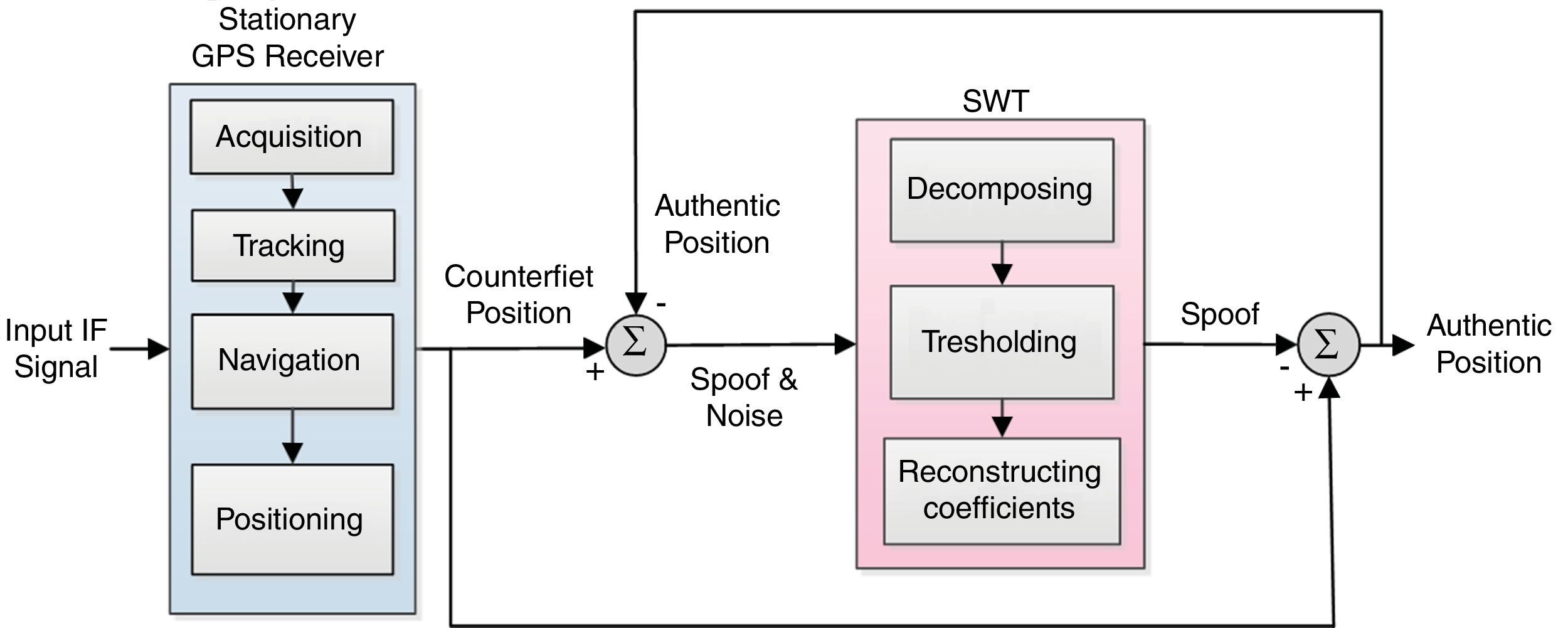
3.3Performing the proposed spoof-reduction algorithm in position stageThis section describes a novel solution that decreases spoofing effect on the navigation part of GPS receiver. When the received signal is a mixture of both desired signal and spoofing which can be produced by intentional or unintentional sources, an appropriate algorithm under certain circumstances can be designed to reduce spoofing effect. In this condition, the main objective of interference cancelation is to estimate the troublemaker signal and then subtract it from the input signal that is a combination of the original and interference signals. Figure 1 describes the suggested algorithm in details when a spoofing attack is recognized. The theoretical foundation of this algorithm is based on the following discussion, it includes six main steps:

Step 1: Immediate interference determination
Recognition is the most important point before executing the mitigation algorithm. The detector determines the start time of mitigation procedure. The last authentic position before detection can be modeled as:
PosA(t) contains the correct position PosR has wideband additive noise, N is functions in time t to be sampled. N incorporates all sources of un-spoofing interferences over the channel. GPS noise and interference signals tend to fall into the same range of frequencies. In this case, the position solution after acquiring spoofing signal will be defined as follows:where PosS indicates the counterfeit location coordinates. In similar scenarios, without a reliable spoof detector, a new position error can be produced due to the spoof-reduction algorithm. Of course, our proposed methodology does not make position errors in the case of executing on genuine GPS data, but it will increase the processing time.

Step 2: Subtracting last authentic position from current fake coordinates to extract “Spoof & Noise”
Eq. (4) shows the difference of coordinates before and after spoofing detection.
where P˜osS(t) is extracted position error and P˜osR(t) is the last position solution before spoof detection in the first epoch and estimated authentic position from the previous epoch in later epochs.
Step 3: Decompose the “Spoof & Noise” with SWT
PosSN(t) is applied to SWT, immediately after spoof recognition. Now the de-noising process attempts to modify wavelet coefficients so that noise is extracted from the original signal, where the unknown signal PosS(t) must be retrieved from the noisy data PosSN(t). N(t) is a white Gaussian noise with a noise level of σ2. The reconstruction of PosSN(t) in the wavelet domain means the translation of all the wavelet coefficients of N(t) to zero value by a proper threshold.
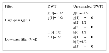
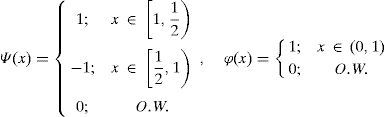
As mentioned in Section 3.2, we used one-dimensional SWT in (X, Y, Z) three dimensional coordinates, because the signal parameters in three dimensional coordinates are processed simultaneously. Next important step is to choose the best mother wavelet, which usually depends on application. Here we choose the Haar wavelet as the mother wavelet. This wavelet is a simplest possibility wavelet and easy to implement illustrating the desirable properties of wavelets in general. First, it can be performed in O(n) operations; second, it captures not only a notion of the frequency content of the input, through examining it at different scales, but also contains temporal content, i.e., the times at which these frequencies occur (Donoho & Johnstone, 1994). Table 1 lists the corresponding coefficients of the up-sampled g[n] and h[n] for Haar mother wavelet at level 2.
SWT of Haar wavelet with scaling function can be expressed by Eq. (5):
Step 4: Thresholding the operation to change the coefficients obtained from previous stage
Thresholding is performed by determining the method of reformation coefficients and the noise modeling (Mosavi & Azarbad, 2013). Mainly, there are two types of hard and soft thresholding. Hard thresholding zeros out small coefficients resulting in an efficient representation which is not proper for de-noising. Soft thresholding decreases coefficients by the threshold value to exceed them for softening. Generally, this is used for de-noising applications (Jumah, 2013). Here we used a rule of shrinkage to modify the coefficients in step 3 as developed by Borre, Akos, Bertelsen, Rinder, and Jensen (2007).
Step 5: Reconstructing the de-noised SWT coefficients from step 4 to obtain “Spoof”
WT provide spoof error through reconstructing the de-noised SWT coefficients as follows:
where A2 is approximate coefficient of SWT at level 2 and φ is the scaling function. It is worth emphasizing that in absence of other interferences, spoofing error is the only inaccuracy of the position estimations, after the de-noising procedure is finished. As mentioned in the previous subsection, the SWT is an inherent redundant scheme, as each set of coefficients contains the same number of samples as the input and therefore, for a decomposition of N levels, there is a redundancy of 2N. As a result, the reconstruction procedure is different from the standard WT (Mosavi & Azarbad, 2013).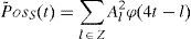
Step 6: Reducing the extracted spoof error from the primary position to get “authentic position”
As explained above, the noise of the input signal with spoof part is applied to SWT, and extracted by de-noising after passing of the above steps. Finally, the algorithm subtracts the extracted disturbance from the primary fake position solution to get authentic position information for the GPS navigation as:

As a privilege from Figure 1, this algorithm makes no muddle when applied to legacy signal. In other words, if the detector announces a false attack alarm and the algorithm is activated in normal mode, the final position will be genuine anyway. Moreover, location accuracy may be modified owing to the de-noising procedure.
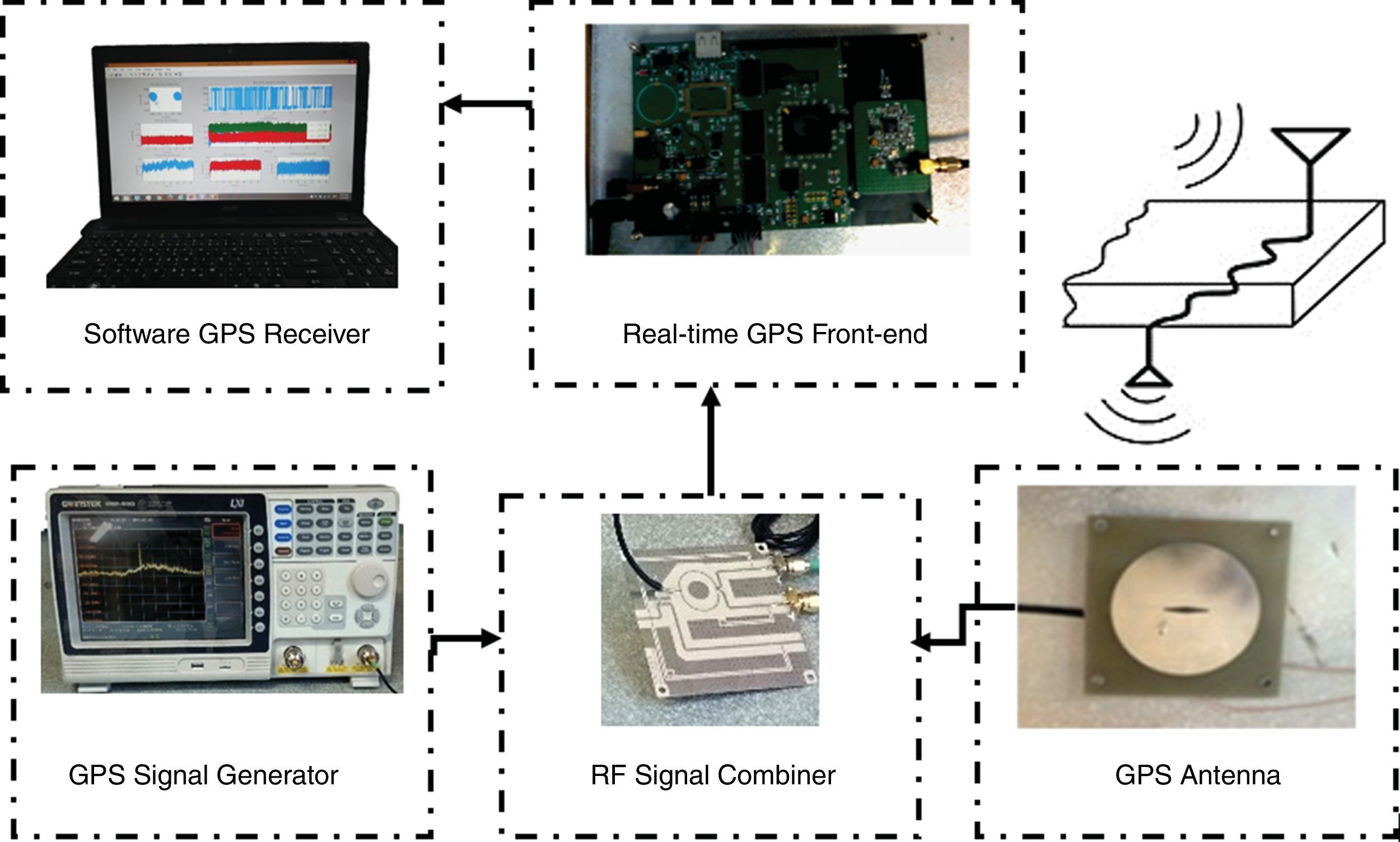
4Results and analysisIn order to investigate the performance of the suggested technique, we have implemented and tested our proposed plan on batch laboratory and measurement data sets separately (Baziar et al., 2015). Laboratory platform scheme of the total system is demonstrated in Figure 2. The system was implemented as a SDR in Matlab. All processing was done on a laptop Acer 5755G with i7 2.2GHz CPU. This section will describe the data collection process and then provide results of compensating. During different tests, we almost compensate spoofing error, entirely.
4.1Counterfeit data generation
The fraudulent data collection procedure provides a batch data set. In this procedure, two parameters are effective: delay time and amplitude of delayed signal. Since the power of GPS signal is low on the surface of the Earth, the power of the constructed signal can be increased and adjusted higher than the authentic to successfully mislead the target receiver and prevent simple detection (Baziar et al., 2015). The first laboratory spoofing data set is produced from IF signal from the collected data set.
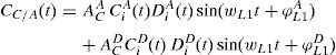
We combined a SDR with a transmitting RF front-end for practical implementation of an intermediate attack. The processed signal in single-frequency GPS receivers takes the form:
where AC is C/A code amplitude, Ci(t) is ith PRN C/A code, Di(t) is the ith PRN navigation message, ωL1 is the angular frequency of L1 signal and φL1 is L1 signal phase. The constructed counterfeit signal can be written as:where A and D present the authentic and delayed signals, respectively. CC/A(t) is indeed spreading signal for deception. For generating this signal, we need to take the legacy signal as delayed one. After providing the faked signal and transmitting, the received signal to the victim receiver can be expressed as Eq. (10) and modified as Eq. (11) (Baziar et al., 2015):

In the second data set, we tried to release from quantization error due to the A/D in the front-end module. For this purpose, we decided to combine the RF signals instead of IF signals. With regard to our laboratory equipment, this can be feasible only with a GPS signal simulator. In this way, the delayed signal described above was emerged from a simulator. In this scenario, it is generally assumed that simulator's output is much the same signal directly taken from the GPS antenna. The corrupted signal in this attack can be expressed as:
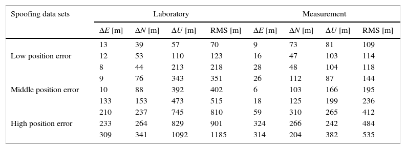
where α is amplification factor and equals to 2 here and τ is the delay of counterfeit signal. According to the above-mentioned modeling, αS(n−τ) is actually considered as interference element. After the RF input signal is converted into a digital IF signal and before satellite acquisition, spoofing attack is applied to the data. In this way, three category spoofing data are yielded. Table 2 lists some examples of each group and specifies the position error in East, North and Up (ENU) coordinates.
Details of spoofing data sets.
| Spoofing data sets | Laboratory | Measurement | ||||||
|---|---|---|---|---|---|---|---|---|
| ΔE [m] | ΔN [m] | ΔU [m] | RMS [m] | ΔE [m] | ΔN [m] | ΔU [m] | RMS [m] | |
| Low position error | 13 | 39 | 57 | 70 | 9 | 73 | 81 | 109 |
| 12 | 53 | 110 | 123 | 16 | 47 | 103 | 114 | |
| 8 | 44 | 213 | 218 | 28 | 48 | 104 | 118 | |
| Middle position error | 9 | 76 | 343 | 351 | 26 | 112 | 87 | 144 |
| 10 | 88 | 392 | 402 | 6 | 103 | 166 | 195 | |
| 133 | 153 | 473 | 515 | 18 | 125 | 199 | 236 | |
| High position error | 210 | 237 | 745 | 810 | 59 | 310 | 265 | 412 |
| 233 | 264 | 829 | 901 | 324 | 266 | 242 | 484 | |
| 309 | 341 | 1092 | 1185 | 314 | 204 | 382 | 535 | |
Where RMS refer to position's difference between navigational solutions based on authentic and spoof signals, ΔU is height difference and ΔE and ΔN are varied in surface horizons. Low position error includes positioning error less than 300 meters. Spoofing between 300 and 500m called intermediate spoofing. Errors higher than 500m are considered as high position error. Through analyzing the effect of spoofing in the receiver software, we discovered that spoofing attacks mainly distort visible satellites, pseudo-ranges and satellites’ position. Since the navigation solution and GPS coordinates are based on these specifications, noticeable spoofing errors are seen. The remainder of this section will analyze acquired results of the algorithm.
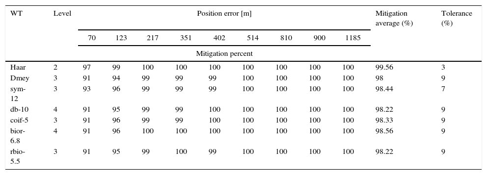
4.2Test results of laboratory spoofing dataThe proposed algorithm was applied to laboratory spoofing data set and then results were stored. The efficiency of the suggested technique implementation in mitigation of position error is illustrated in Table 3. Each row of Table relates to the results of the proposed anti-spoofing algorithm by a specified mother wavelet on different spoofing data set. The “mitigation average” column indicates mean of reduction percentage for every WT. The difference between the highest and the lowest reduction percentage of different spoofing data for each WT reported as “Tolerance”. As it can be seen from Table 3, Haar WT at level 2 has the best operation in average for different data sets, which mitigates interference within an average of 99.56% and a tolerance of 3%.
Details of interference rejection algorithm performance on laboratory spoofing data.
| WT | Level | Position error [m] | Mitigation average (%) | Tolerance (%) | ||||||||
|---|---|---|---|---|---|---|---|---|---|---|---|---|
| 70 | 123 | 217 | 351 | 402 | 514 | 810 | 900 | 1185 | ||||
| Mitigation percent | ||||||||||||
| Haar | 2 | 97 | 99 | 100 | 100 | 100 | 100 | 100 | 100 | 100 | 99.56 | 3 |
| Dmey | 3 | 91 | 94 | 99 | 99 | 99 | 100 | 100 | 100 | 100 | 98 | 9 |
| sym-12 | 3 | 93 | 96 | 99 | 99 | 99 | 100 | 100 | 100 | 100 | 98.44 | 7 |
| db-10 | 4 | 91 | 95 | 99 | 99 | 100 | 100 | 100 | 100 | 100 | 98.22 | 9 |
| coif-5 | 3 | 91 | 96 | 99 | 99 | 100 | 100 | 100 | 100 | 100 | 98.33 | 9 |
| bior-6.8 | 4 | 91 | 96 | 100 | 100 | 100 | 100 | 100 | 100 | 100 | 98.56 | 9 |
| rbio-5.5 | 3 | 91 | 95 | 99 | 100 | 99 | 100 | 100 | 100 | 100 | 98.22 | 9 |
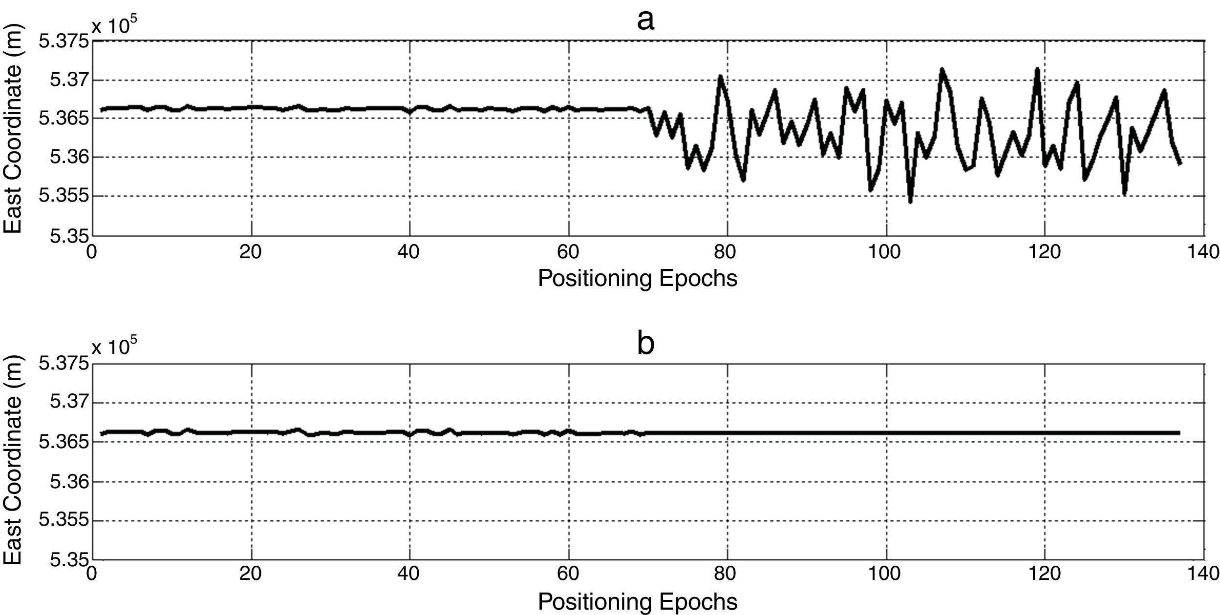
To verify the performance of the proposed algorithm, the operation of a randomly selected data set is evaluated below. Coordinate variations before and after applying the suggested algorithm are depicted in Figure 3. As observed from the figure, in the case of quick detection, the proposed interference canceling technique nullifies powerfully the undesirable deviation caused by the attack.
4.3Test results of measurement spoofing data
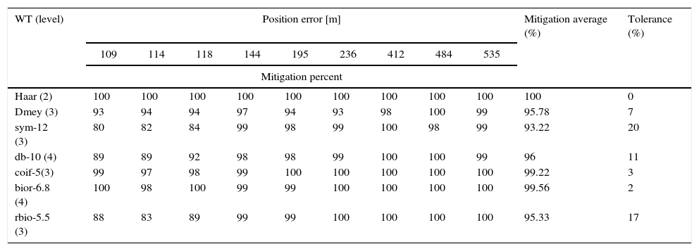
Table 4 reports the results of the interference rejection algorithm on experimental data sets. Similar to laboratory data sets, the best results can be selected easily in Table 4. It is evident from Table 4 that the Haar WT that completely compensates spoofing error of all data sets.
Details of interference rejection algorithm performance on experimental data sets.
| WT (level) | Position error [m] | Mitigation average (%) | Tolerance (%) | ||||||||
|---|---|---|---|---|---|---|---|---|---|---|---|
| 109 | 114 | 118 | 144 | 195 | 236 | 412 | 484 | 535 | |||
| Mitigation percent | |||||||||||
| Haar (2) | 100 | 100 | 100 | 100 | 100 | 100 | 100 | 100 | 100 | 100 | 0 |
| Dmey (3) | 93 | 94 | 94 | 97 | 94 | 93 | 98 | 100 | 99 | 95.78 | 7 |
| sym-12 (3) | 80 | 82 | 84 | 99 | 98 | 99 | 100 | 98 | 99 | 93.22 | 20 |
| db-10 (4) | 89 | 89 | 92 | 98 | 98 | 99 | 100 | 100 | 99 | 96 | 11 |
| coif-5(3) | 99 | 97 | 98 | 99 | 100 | 100 | 100 | 100 | 100 | 99.22 | 3 |
| bior-6.8 (4) | 100 | 98 | 100 | 99 | 99 | 100 | 100 | 100 | 100 | 99.56 | 2 |
| rbio-5.5 (3) | 88 | 83 | 89 | 99 | 99 | 100 | 100 | 100 | 100 | 95.33 | 17 |
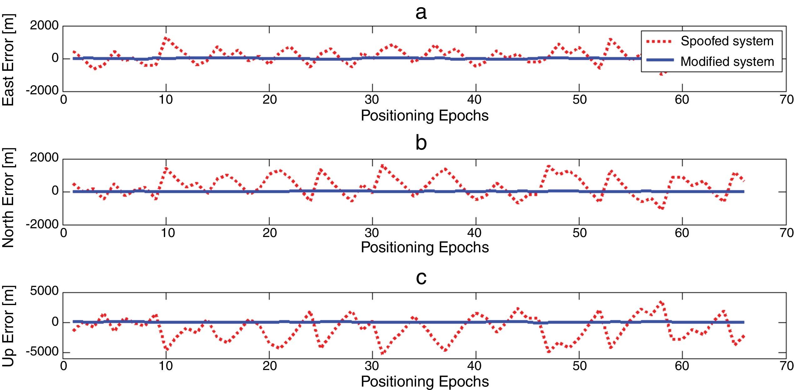
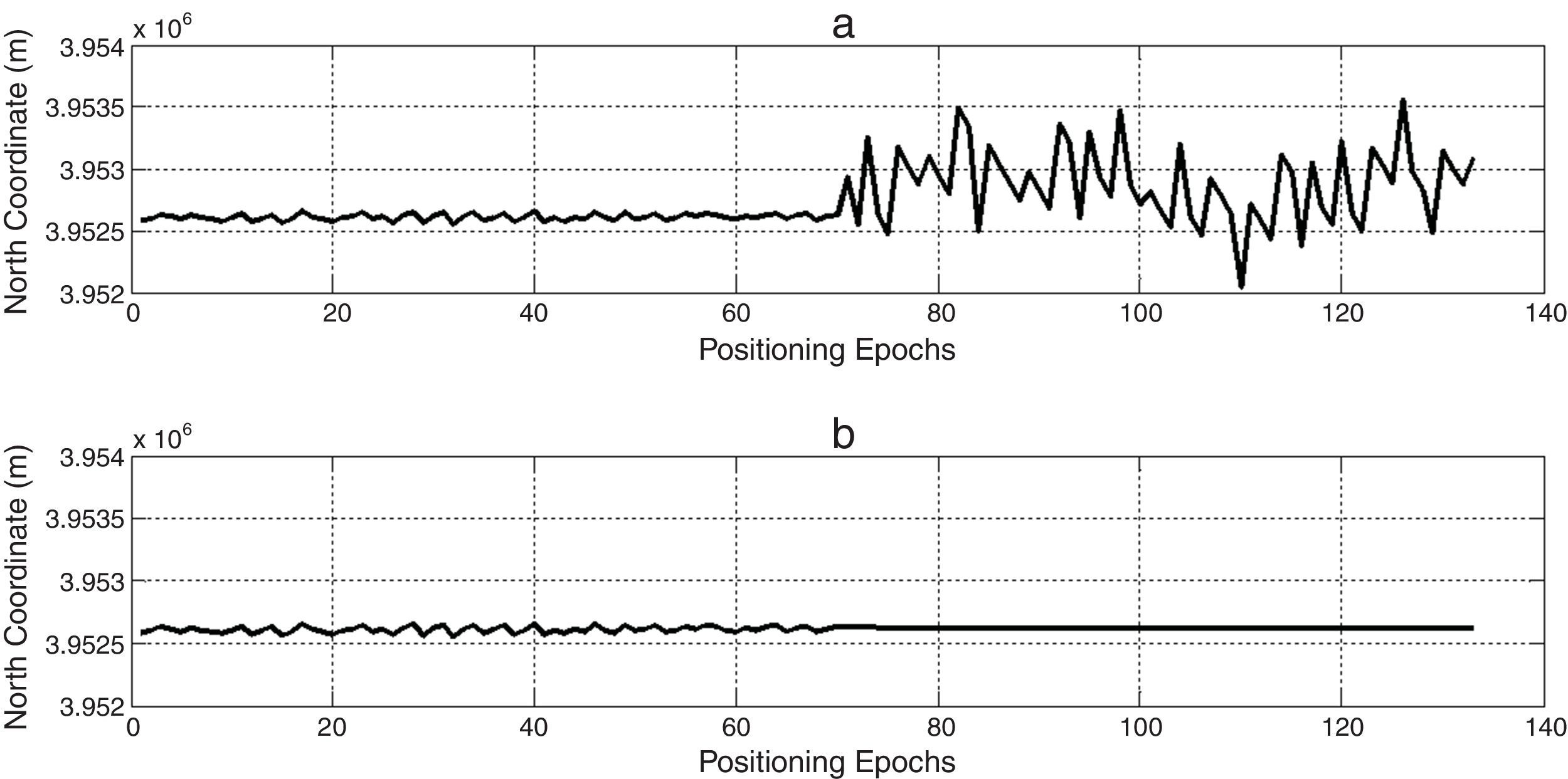
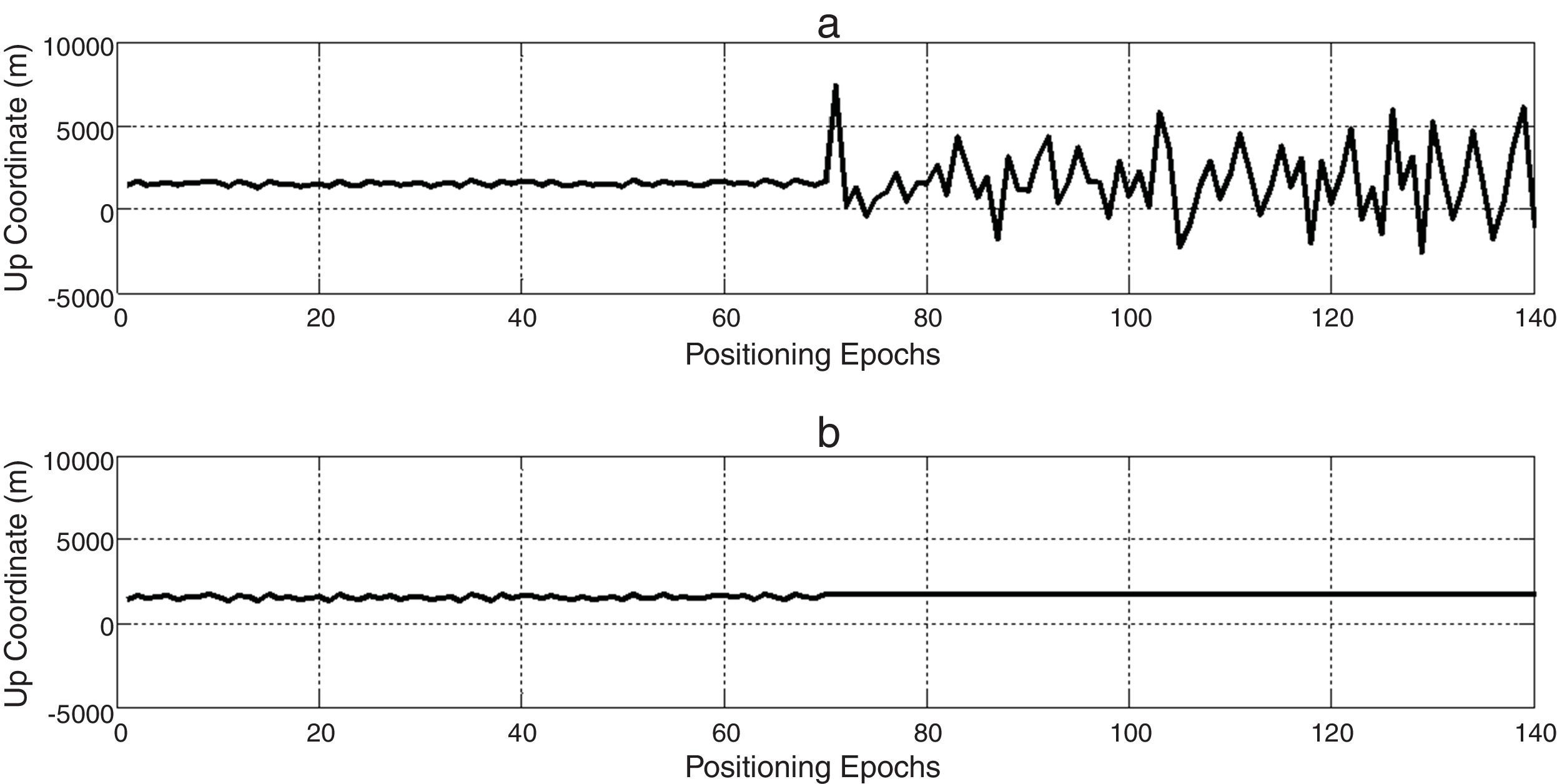
This section also presents some test scenarios that have been used for evaluating the performance of the suggested algorithm on measurement data set. Figures 4–6 plot ENU coordinates of a sample example of under test data set before and after the attack. It is clear from the figures, initial 70 epochs belong to authentic data. At epoch 71, the anti-spoofing algorithm is active after intermediate attack detection.
 before and (b) after applying the proposed algorithm.")
 before and (b) after applying the proposed algorithm.")
 before and (b) after applying the proposed algorithm.")
In order to noise obviation, authentic position coordinates in the first 70 epochs are averaged and used as genuine position in anti-spoofing algorithm, spatially if there is not an intermediate detection mechanism. In this way, not only the abnormal deviations of position coordinates due to spoofing have been compensated, but also wavelet de-noising process smoothes authentic position observations to more increase navigation accuracy. Finally, we could express a wholly interference reduction technique.
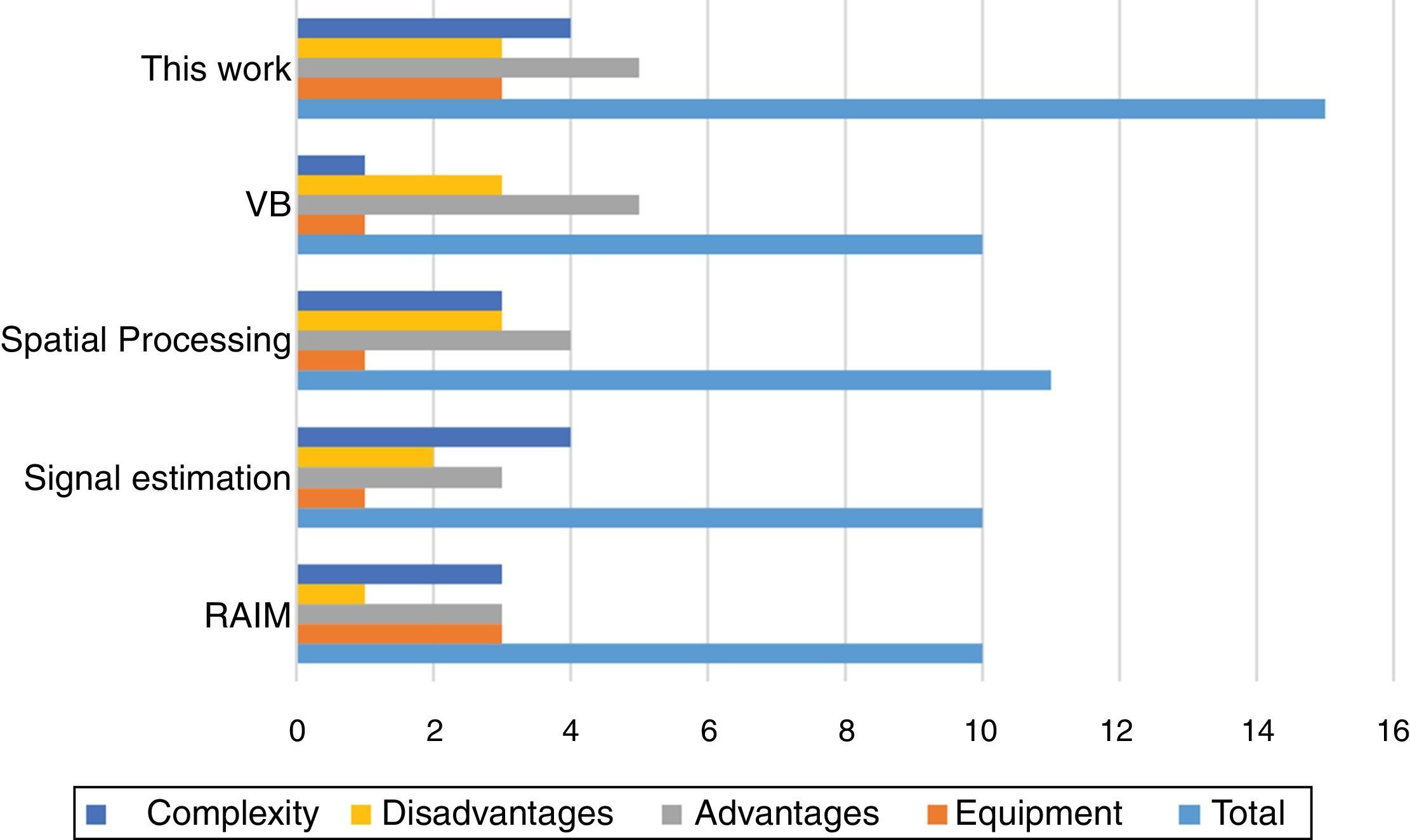
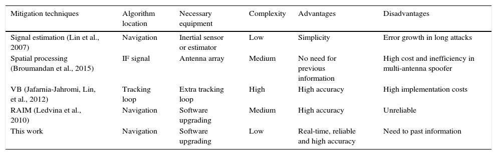
4.4Performance comparisonBecause of dissimilarity between of proposed detection and mitigation methods with existing ones, accurate comparison with prior works is difficult. Table 5 produces a comparative evaluation of new and previous mitigation methods based on complexity, necessary equipment, advantages and disadvantages (Jafarnia-Jahromi, Broumandan, Nielsen, & Lachapelle, 2012).
Comparative performance of spoof mitigation techniques.
| Mitigation techniques | Algorithm location | Necessary equipment | Complexity | Advantages | Disadvantages |
|---|---|---|---|---|---|
| Signal estimation (Lin et al., 2007) | Navigation | Inertial sensor or estimator | Low | Simplicity | Error growth in long attacks |
| Spatial processing (Broumandan et al., 2015) | IF signal | Antenna array | Medium | No need for previous information | High cost and inefficiency in multi-antenna spoofer |
| VB (Jafarnia-Jahromi, Lin, et al., 2012) | Tracking loop | Extra tracking loop | High | High accuracy | High implementation costs |
| RAIM (Ledvina et al., 2010) | Navigation | Software upgrading | Medium | High accuracy | Unreliable |
| This work | Navigation | Software upgrading | Low | Real-time, reliable and high accuracy | Need to past information |
For reliable and correct judgment, we assigned a numerical value to any feature. The worst and best case is considered for any future; 0 score is dedicated for worst state and 5 score for the best. Then, depending on algorithm operation a number from 0 to 5 is assigned to any feature. For example, about “necessary equipment” feature, an algorithm earns 5 scores if needed no extra equipment, and in the case of necessity to basal changes in receiver structure, it takes 0 scores. Results of numbering are illustrated in Figure 7. As it can be seen, the proposed algorithm gets 12 points affirming it is better than others. Signal estimation (Lin et al., 2007) and VB (Jafarnia-Jahromi, Lin, et al., 2012) methods are implemented in tracking loop. The first one is not effective for long attacks and the second one makes a massive change in the receiver tracking loop structure. Spatial processing (Broumandan et al., 2015) is an effective and reliable technique, but because of adding extra hardware, have high implementation costs, too (Magiera & Katulski, 2015). New RAIM methods (Ledvina et al., 2010) are being developed, but these algorithms are complex and may be difficult to implement robustly. If such algorithms to be succeed, typically they must achieve detection at the moment of signal drag-off, which degrades their robustness. As it can be seen, the overall effectiveness of the proposed method is superior to others. In addition to the benefits of the previous methods, suggested technique in this paper requires no additional hardware and has simpler implementation, yet it is an accurate method.

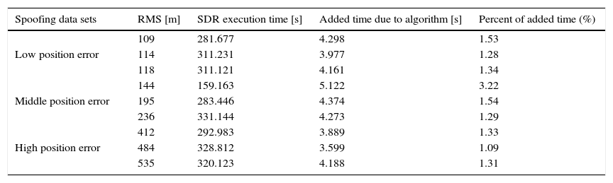
Moreover, unlike the other techniques, success of this algorithm does not depend on the kind of attack. Time complexity of implemented algorithm in Matlab software is shown in Table 6. As it can be observed, execution time differs for various data sets. This is due to difference of line-of-site satellites for each data set. Obviously, many satellites take longer time to execute. For example, spoof data with 109m position error takes 281.677s. After implementing, execution time increases as 4.298s that equates with 1.53% growth. In this way, it is inferable that the overall effectiveness of the proposed method is superior to others. Even though, it needs modification at navigation stage.
Time complexity of proposed method.
| Spoofing data sets | RMS [m] | SDR execution time [s] | Added time due to algorithm [s] | Percent of added time (%) |
|---|---|---|---|---|
| Low position error | 109 | 281.677 | 4.298 | 1.53 |
| 114 | 311.231 | 3.977 | 1.28 | |
| 118 | 311.121 | 4.161 | 1.34 | |
| Middle position error | 144 | 159.163 | 5.122 | 3.22 |
| 195 | 283.446 | 4.374 | 1.54 | |
| 236 | 331.144 | 4.273 | 1.29 | |
| High position error | 412 | 292.983 | 3.889 | 1.33 |
| 484 | 328.812 | 3.599 | 1.09 | |
| 535 | 320.123 | 4.188 | 1.31 |
This paper contains a review of literature pertaining to spoofing attacks, interference rejection techniques and WT with specific interest in their strong point and problems. Moreover, a new interference mitigation technique using wavelet de-noising has been proposed. Two types of counterfeit data set are used for evaluating the proposed algorithm. Designing this approach has been repeatedly tested and its performance was demonstrated in terms of position errors. It can be seen from the results that the RMS values of the spoofing errors have been reduced fully after applying the corrections, which looks on as outstanding performance in interference suppression field. Finally, as a great pleasure, the civil stationary GPS receivers can be immediately modified to exploit the proposed authentication strategy. Moreover, it is expected that because of executing on position solution the proposed technique can be effective in other kinds of interference, which will be investigated in future works.
Conflict of interestThe authors have no conflicts of interest to declare.
Peer Review under the responsibility of Universidad Nacional Autónoma de México.