


Thin film multiferroic composites, with a high quantity of interfaces between the different materials, represent a more feasible alternative to single phase systems in which the multifunctional response is usually hampered due to intrinsic physical constraints. Nowadays some of these composites can be produced by applying deposition techniques such as PLD, CVD, MBE or the like, which allow a high degree of crystallographic control. However, despite their effectiveness, all these techniques also involve a high consumption of energy in terms of temperature and/or vacuum. Within this frame, the present contribution proposes a sustainable chemical solution deposition process to prepare thin films of the multiferroic BiFeO3–Bi4Ti3O12 composite system. More specifically an aqueous solution-gel plus spin-coating methodology is employed which also avoids the organic solvents typically used in a conventional sol–gel method, so further keeping an eye on the environmentally friendly conditions. Attempts are conducted that demonstrate how by systematically controlling the processing parameters it is possible to obtain thin film composites with a promising 3-3 type connectivity at temperatures as low as 600°C.
Los materiales compuestos (composites) multiferroicos en forma de lámina delgada y con un gran número de intercaras entre los distintos componentes, representan una alternativa más práctica y viable frente a los sistemas monofásicos, en los cuales la respuesta multiferroica se encuentra típicamente impedida debido a restricciones físicas de carácter intrínseco. Actualmente algunos de estos composites son obtenidos mediante diversas técnicas de deposición tales como PLD, CVD, MBE o similares, las cuales permiten un alto grado de control a nivel cristalográfico. No obstante, a pesar de su efectividad, todas estas técnicas también engloban un alto consumo de energía en términos de temperatura y/o vacío. En este contexto, el presente trabajo de investigación propone un método de deposición química en disolución para obtener láminas delgadas del sistema multiferroico compuesto BiFeO3-Bi4Ti3O12. En concreto se plantea la utilización de una metodología disolución-gel en medio acuoso seguida de deposición por spin coating, metodología con la que además se evita el empleo de los disolventes orgánicos típicamente utilizados en un método sol-gel convencional y que por tanto acentúa el carácter sostenible del proceso. Para ello se han llevado a cabo diferentes experimentos con los cuales se pone de manifiesto cómo llevando a cabo un control sistemático de las distintas variables del proceso, es posible obtener composites en forma de lámina delgada con una prometedora configuración 3-3 a temperaturas no superiores a 600°C.
By definition, a multiferroic material exhibits the coexistence of at least two of the so-called ferroic orders: ferroelectricity, ferromagnetism and ferroelasticity [1]. Nowadays, single-phase oxide systems can be prepared, in which an intrinsic multiferroic order is allowed based on symmetry arguments [2–5]. However, constraint considerations associated with the simultaneous presence of magnetism and ferroelectricity typically lead to low critical temperatures in those single-phase structures, making their multiferroic response unpractical. Such limitations have redirected efforts to a more realistic approach, which is the fabrication of heterogeneous composite systems [6–10]. In the composite arrangement, the different order parameters need not to coexist in the same phase, while the symmetry rupture ensued from the different symmetries of the heterostructure would originate an extrinsic coupling at the interface. Connectivity between different phases is a key feature in property development in multiphase solids, since physical properties can change by orders of magnitude depending on the manner in which connections are made [11]. For example, in a two-phase composite, each phase may be self-connected in zero, one, two, or three dimensions, this rendering up to ten different connectivities designated as 0-0, 1-0, 2-0, 3-0, 1-1, 2-1, 3-1, 2-2, 3-2, and 3-3. In this frame, nanostructured composites with large surface areas such as core–shell particulates (3-0) [12], nanofibers embedded in a matrix (3-1) [13] or multilayer thin films arrays (2-2) can be especially effective for its possible application in miniaturized devices [14–17].
Well-defined layered composites, with a precise control over the interfaces, can now be fabricated by using sophisticated thin film deposition technologies like CVD, PLD, MBE or RF magnetron sputtering. All these techniques however involve high energy operations in terms of temperature and/or vacuum, unavoidably exerting a harmful contribution to the global climate, but also restraining the spectrum of accessible materials (e.g. non-volatile compounds) [18,19]. Visibly superlative benefits, such as simplicity, economic efficiency, or environmental benevolence can be achieved from the use of feasible sustainable processing technologies (e.g. wet chemical methods), if and when a well-matched interface between the two phases would be still guaranteed [14]. In this view, a chemical solution deposition based on a combined sol–gel plus spin-coating procedure is becoming an effective alternative with which a precise control of the interface can be achieved by carefully controlling the experimental conditions. This technique entails a non-vacuum and low-temperature synthesis methodology based on a solution processing, which starts with the synthesis of precursor solutions, followed by coating rotating substrates with these precursors, resulting in a thin film deposit (spin coating). The routine concludes with a low to mild temperature thermal treatment, which decomposes the organic components of the precursor solutions, crystallizes the desired compound, and consolidates the films. The main limitation of this methodology might be found in the implicit toxicity of certain organic solvents, involved in the synthesis of the precursor solutions. However, this restraint can be overcome by applying the so-called aqueous solution-gel methodology [20]. In this case, the precursors used are aqueous solutions, in which the metal ions of interest are stabilized by complexation with chelating ligands such as peroxide and citrate. These homogeneous precursor solutions are stable in ambient conditions for extended periods of time. When the water is evaporated from these optimized solutions an amorphous, solid gel precursor is obtained. Alternatively the precursor solutions can be applied for spin coating onto a suitable substrate in order to obtain thin films. After gelation or deposition, organic components are thermo-oxidatively removed by an optimized thermal treatment to yield the phase pure metal oxide. This route provides excellent compositional control, due to the high degree of homogeneity, is inexpensive and allows uncomplicated deposition of films with a thickness ranging from several hundreds of nm down to a few nanometres [21].
Accordingly, in the present contribution the aqueous solution-gel deposition methodology is applied to the preparation of composite BiFeO3–Bi4Ti3O12 thin film assemblies. This particular binary system has been recently considered as a promising multiferroic candidate in a composite configuration [22]: due to similarities in the involved crystal structures (both oxides comprise perovskite-like constituent units), a well-matched interface is presumed and an effective coupling can be achieved, provided that the diffusion processes between both materials are properly avoided [23]. Moreover, in this work we deal with BiFeO3 and Bi4Ti3O12 doped compositions; specifically we use samarium to dope both oxides (Bi0.88Sm0.12FeO3 and Bi3.2Sm0.8Ti3O12 nominal compositions, respectively) since it has been demonstrated recently that this dopant can be crucial for obtaining an enhanced multiferroic response in the system [24,25].
ExperimentalMaterials and methodsTwo different set of samples were prepared in this work to test the ability of the aqueous solution-gel plus spin-coating methodology in producing thin films, namely individual Sm-BiFeO3 films (SmBFO, as reference sample) and composite Sm-BiFeO3+Sm-Bi4Ti3O12 films (SmBFO-SmBiT). The aqueous solution-gel spin-coating method comprises a first stage in which precursors of the metals of interest are individually prepared in an aqueous medium, by dissolving the respective metal salts. This dissolution process usually involves the use of chelating agents to form stable complexes. Citric acid and derived citrates are among the most commonly used for this purpose [26–29]. In the BiFeO3–Bi4Ti3O12 system under study, the following starting materials were used: iron (III) citrate hydrate (Fe(C6H5O7)3, 98%, Acros), bismuth (III) citrate (Bi(C6H5O7)3, 99.99%, Aldrich) and titanium (IV) isopropoxide (Ti(iOPr)4, 98+%, Acros). Samarium (III) oxide (Sm2O3, 99.9%, Strem Chemicals) was used as the samarium source. In addition to the metal precursors, ammonia (NH3, 32% in H2O, extra pure, Merck), ethanolamine (C2H7NO, redistilled, 99.5+%, Aldrich), citric acid (C6H8O7, 99%, Aldrich) and hydrogen peroxide (H2O2, 35wt.% in H2O, p.a., stabilized, Acros) were employed to assist in the dissolution process. In a second stage, the individual solutions are mixed in the corresponding stoichiometric ratios to yield multi-metal ion precursor solutions (one for SmBFO and one for SmBiT), and finally, thin layers are subsequently spin coated using a spin coating machine (Laurell Technologies), operating under continuous N2 flow.
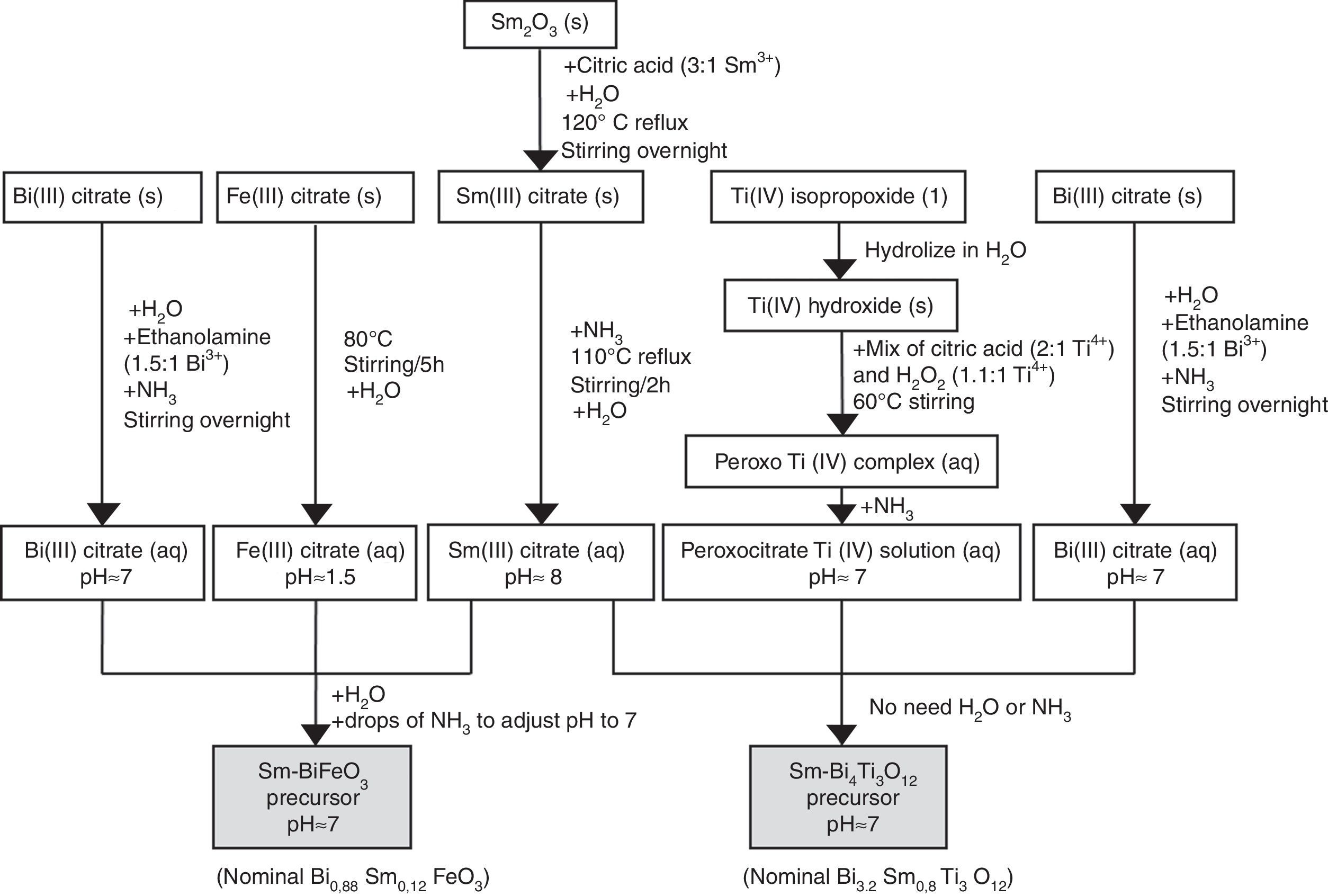
Synthesis of the precursor solutions by an aqueous solution-gel methodologyFig. 1 summarizes the different steps conducted for obtaining the multimetal precursor solutions of SmBFO and SmBiT. The first one is prepared by a combination of aqueous monometal precursor solutions of iron (III) citrate, bismuth (III) citrate and the as-prepared samarium (III) citrate, while the second one requires the combination of monometal aqueous precursor solutions of bismuth (III) citrate, and the as prepared peroxocitrato-Ti (IV) complex and samarium (III) citrate. In the following, the process necessary to prepare the aqueous monometal precursors solutions of Fe (III), Bi (III), Ti (IV) and Sm (III) is described in detail:
- 1)
The Fe (III) aqueous solution was prepared by refluxing the required amount of iron (III) citrate in water at 80°C overnight [28]. As a result, a stable citrate precursor with pH 1.5 was obtained. This pH should not be increased with the addition of ammonia, as this could lead to precipitation. Indeed, it can be deduced from the pM–pH diagram of Fe (III) that in the presence of citrate ligands Fe(OH)3 is formed at higher pH [30]. Once the entire amount of iron (III) citrate was dissolved, the solution was filtered using a membrane filter (Gelman sciences, supor, 0.1μm) to remove possible particles in suspension such as dust, impurities or undissolved fractions. Subsequently the exact concentration was determined by ICP-AES, since it is assumed that during its preparation, small experimental errors can be produced which make the concentration slightly lower. This technique allows to accurately determine the concentration of each solution, something which is essential to find out how much of each precursor solution is needed to form the multimetal solutions. In this case the exact concentration obtained for this solution was 0.377±0.002mol/L.
- 2)
Regarding the Bi (III) aqueous solution, bismuth citrate is known to be only slightly soluble in water, but its solubility can be increased by addition of ammonia [31]. However, even in this case, the stability of the solution in water remains low, which may result in a precipitation shortly after being prepared. The unstable resulting solution therefore needs the addition of ethanolamine to increase its stability, avoiding quick precipitation. Specifically by adding ethanolamine in a 1.5:1 molar ratio against Bi3+ together with ammonia, the obtained bismuth citrate aqueous solution is now stable for several months [26]. As was done for the Fe (III) aqueous solution, a 0.1μm porous filter was used to filter the solution and the exact concentration was determined by ICP-AES giving a 0.737±0.005mol/L concentration.
- 3)
For the Sm (III) aqueous solution, a mixture of Sm2O3 and citric acid powders (3equiv. with respect to Sm3+) and a small amount of water was initially required. The mixture was refluxed overnight at 120°C while stirring to form the solid Sm (III) citrate and then NH3 is added to increase the pH up to 12. During a subsequent refluxing and stirring step at 110°C for 2h, this pH value decreased again to 8. The solution was filtered as the others to finally determine the exact concentration by ICP-AES giving a concentration of 0.338±0.005mol/L [26].
- 4)
Finally, the Ti (IV) aqueous solution, which was prepared to be combined with Bi (III) solution and Sm(III) solution for the SmBiT multimetal precursor solution, is actually a solution of the water-soluble peroxocitrato-Ti (IV) complex and was obtained by an aqueous-chelated gel route [32,33]. During the first step of this method, hydrolysis of Ti (IV)-isopropoxide in water leads to the precipitation of Ti (IV) hydroxide. The precipitated Ti (IV) hydroxide was then filtered, washed with copious amounts of water and finally allowed to dry under vacuum on a filter paper inside a Büchner funnel. To this precipitate, a mixture of citric acid, in a 2:1 molar ratio against Ti4+, and hydrogen peroxide, in a 1.1:1 molar ratio against Ti4+, was added, while heated to 60°C, resulting in an aqueous peroxocitrate Ti (IV) complex with a strong orange colour. The pH of this resulting Ti (IV) peroxocitrato solution was adjusted to pH=7 by addition of adding NH3. The solution was filtered to finally determine the exact concentration by ICP-AES giving a concentration of 0.081±0.001mol/L.

Once the monometal solutions were obtained, the combination of Fe (III), Bi (III) and Sm (III) aqueous solutions for the multimetal SmBFO precursor requires the addition of some drops of ammonia until pH=7 and the dilution in water to obtain a 0.2M solution concentration. On the other hand, the combination of Bi (III), the peroxocitrato-Ti (IV) complex and Sm (III) for the SmBiT precursor does not need the addition of NH3 due to the neutral pH of the monometal precursors, neither the dilution of water due to the low concentration of the Ti (IV) aqueous solution.
Spin coating and consolidation of the SmBFO and SmBFO-SmBiT thin filmsFor the spin coating process, the different precursor solutions were deposited onto Si/SiO2 (100) oriented substrates. These substrates were initially chosen because their specific orientation favours the subsequent epitaxial growth of the BiFeO3 (perovskite) thin films [34]. In all cases it is crucial to make the surface of the substrate hydrophilic so to achieve a great spread of the aqueous solutions upon deposition [35]. For this reason, the silicon substrates were cleaned by UV/O3 treatment shortly before being placed on the spin coater for the deposition. After that, a standard rotation speed of 3000rpm for 30s, with an acceleration of 1000rpm/s was used. In order to achieve an optimum film thickness, up to five depositions were conducted per experiment (5-layered films), each deposition step being followed by a number of hot plate drying treatments (see results and discussion section). Eventually a thermal anneal at 600°C/1h was applied to the whole assembly to crystalize and consolidate the deposited films. As mentioned above, this whole deposition stage was applied to prepare two different sets of samples: individual SmBFO films (5-layered films) and composite SmBFO-SmBiT (5+5 layered films). For the composite series we proceeded as follows: deposition of the five SmBFO layers onto the substrate, crystallization at 600°C/1h, deposition of the five SmBiT layers and final treatment of the whole assembly again at 600°C/1h. Notice that this is not an arbitrary procedure, and actually the inverse deposition order may lead to unwanted diffusion problems: we have recently demonstrated that annealing the BiFeO3 deposited counterpart (600°C) prior to the deposition of a Bi4Ti3O12 cover, can inhibit any diffusion at the composite interface, whereas heating a first deposited Bi4Ti3O12 cannot prevent the diffusion of iron from a subsequent addition of a BiFeO3 precursor [23].
Characterization techniquesThe precise concentration of the metals in each monometal aqueous precursor solution was determined by ICP-AES using an Optima 3000 equipment, PerkinElmer. The thermogravimetric analyses of the precursors were carried out in a TGA furnace of TA instruments, TGA 951-2000. The film topography was studied by tapping mode atomic force microscopy with a Veeco multimode AFM equipped with quadrex module and the nanoscope III controller, and using etched Si probe tips (Nanosensors, GmbH). X-ray diffraction was used for the study of crystalline phase composition of the samples after sintering using an XRD Bruker D5000 machine. FESEM-EDS analyses were performed on Cold FESEM Hitachi S-4700 microscope.
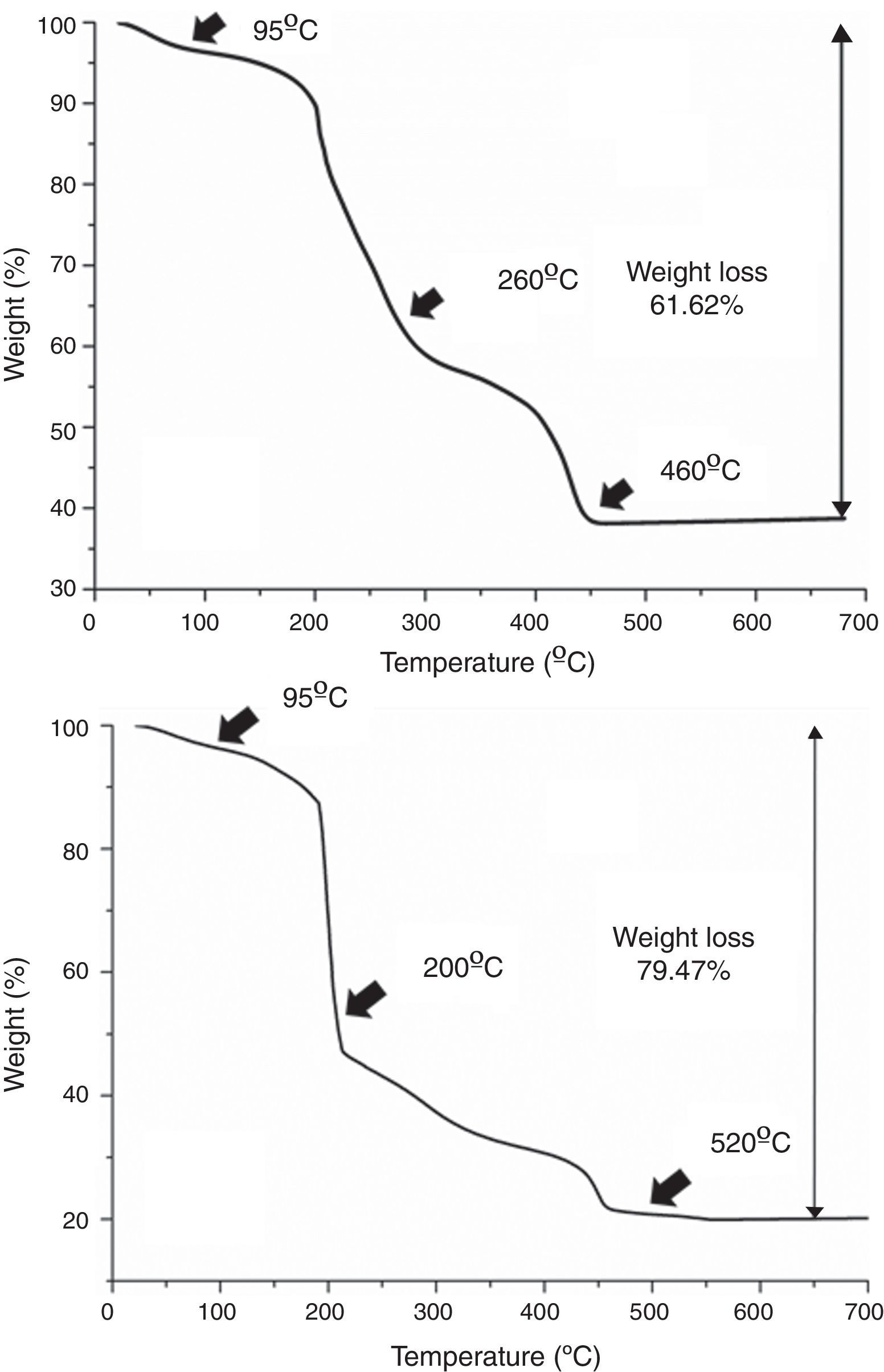
Results and discussionAs mentioned in the experimental section, in all cases each deposition step (i.e. each deposited layer) is followed by a number of hot plate drying treatments. This is done to remove the different compounds used in the preparation of the precursor solutions, viz. ethanolamine, ammonia and citric acid, as well as other as-formed organics and even water remnants that may be trapped in the deposited films. Moreover, the drying treatment should be split in several steps, otherwise morphological defects like micro cracks or blisters could be generated by the sudden evaporation and decomposition of all those compounds simultaneously [36]. The specific steps of the drying process were determined as follows: a small amount of each multimetal solution was evaporated in an air-flushed furnace at 60°C overnight, this leading to a glassy amorphous gel. By grinding the gel in an agate mortar, homogeneous powders were finally obtained that were subsequently analyzed by TGA. The results of these TGA measurements are depicted in Fig. 2 and reveal that both the SmBFO and the SmBiT precursors decompose quite similarly through three major steps. A first weight loss around 95°C is clearly observed in both cases which shall be ascribed to the removal of absorbed water. Following that, different thermal processes overlap in the region between 200 and 500°C but two main slopes can be distinguished: the one around 200–250°C can account for the beginning of the thermal decomposition of citric acid and the citrates [28,37], whereas a possible explanation for the persistence of organic material at temperatures above 450°C could be the formation of nitrogen containing organic compounds, such as (poly)-amides, during the thermal treatment of the gel [29]. So according to these results, after each individual deposition of the multimetal solutions, the following three temperatures were chosen for the hot plate treatments, based on the thermogram: 95°C, 260°C and 460°C for the SmBFO films (Fig. 2a) and 95°C, 200°C and 520°C for the SmBiT films (Fig. 2b). These drying and decomposition steps were all conducted on hot plates for short periods of around 1min and once the total number of depositions was achieved (5 for the SmBFO films, 5+5 for the composites) a final annealing treatment to crystallize the as-prepared film assemblies was conducted at 600°C/1h (also using a hot plate equipped with a top cover). Indeed, this is one of the main advantages of the aqueous solution-gel deposition methodology being tested here, which allows obtaining uniform, homogeneous films at relatively low temperatures [38,39]. Particularly in the case of BiFeO3 based materials, this is even more appealing in order to minimize the indicated volatilization problems and the formation of undesirable secondary phases.
 SmBFO gel and (b) SmBiT gels in air. The arrows indicate the temperatures that were chosen to heat treat the thin films in a stepwise fashion.")
In the first set of experiments, five-layered SmBFO thin films were fabricated and indeed the choice of this number of deposited layers was not arbitrary. On one hand, Pavlovic et al. evidenced that working with just one or two depositions may strongly affect the stabilization of the BiFeO3 perovskite phase, leading to a high amount of secondary phases [40]. Due to the high surface-to-volume ratio and the large exposed surface area of the film geometry, bismuth oxide, being a volatile compound, can easily evaporate during the final anneal. Consequently a loss in stoichiometry (Bi deficiency) would be produced and this would prompt the formation of the characteristic iron-rich Bi2Fe4O9 mullite phase, whose presence is known to be detrimental for the multiferroic properties in this material [41,42]. This situation can be partially amended by reducing the surface to volume ratio, i.e. by increasing the amount of deposited layers, and actually a visible stabilization of the BiFeO3 phase can be again observed already after 5 depositions [40]. However, an increased amount of depositions can also produce the appearance of micro cracks in the films, these being caused by residual stress created due to the mismatch of thermal expansion coefficients between the deposited layers [43] (remember that after each individual deposition the whole film assembly is subjected to a number of drying and decomposition steps).
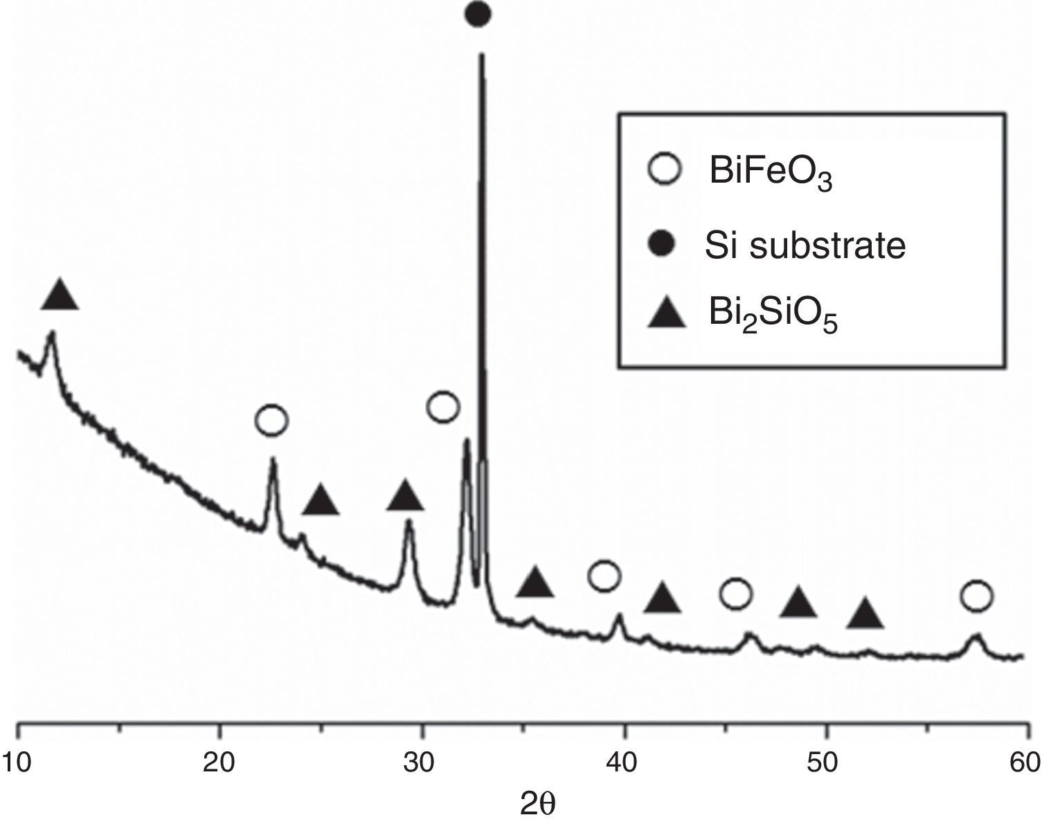
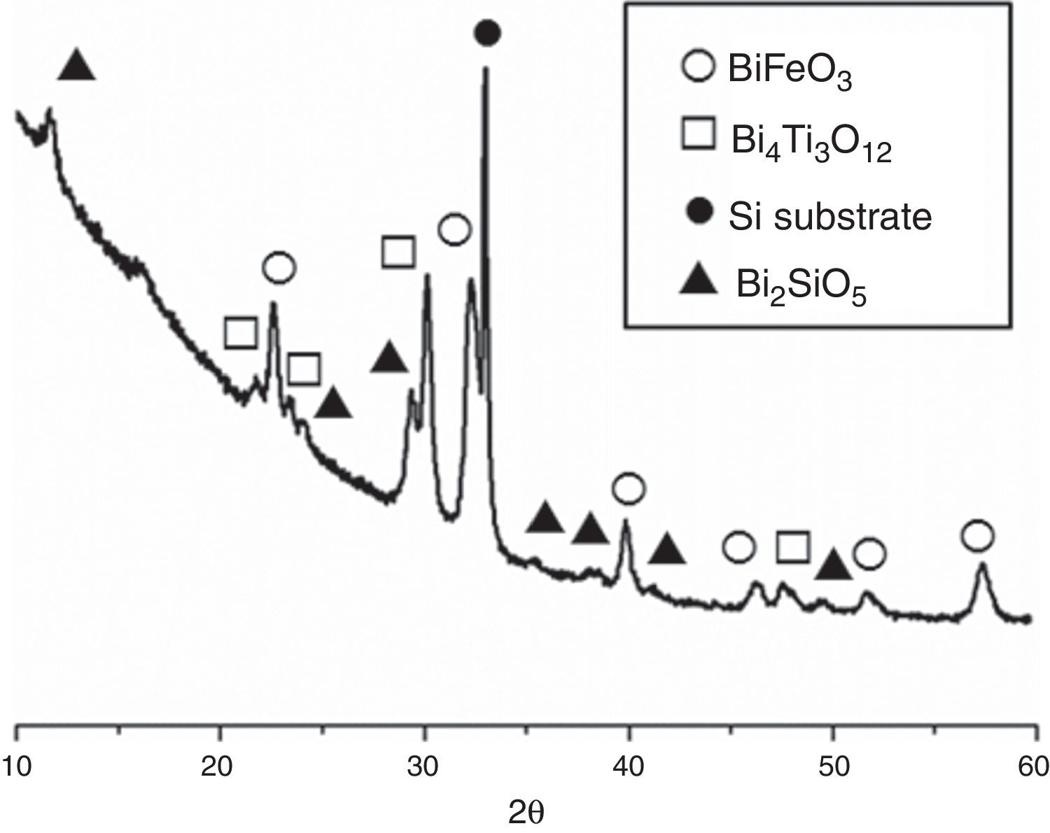
Fig. 3 shows the XRD patterns for the five-layered SmBFO sample, annealed at 600°C during 1h. As observed, it shows a rhombohedral BiFeO3 structure (ICDD file no. 071-2494) as the major phase. It should be mentioned that all the peaks belonging to this phase are visibly displaced to higher angles as a result of the incorporation of the samarium into the perovskite lattice. Besides, no secondary phases such as Fe2O3, Bi2O3 or Sm2O3 are observed, nor even those typically produced during the synthesis of this material such as the mullite Bi2Fe4O9 and the sillenite Bi25FeO39 phases [44]. Instead, a strong peak corresponding to the silicon substrate and peaks attributed to the Bi2SiO5 phase (ICDD file no. 036-0287) are easily detected. The formation of this last phase can be related to some kind of interaction with the substrate and should produce an excess of iron in the sample. However, as indicated, this is not leading to enough amount of Bi2Fe4O9 mullite phase to be detected by the X-ray diffraction measurements. Thus, initially we can assume that the presence of this secondary Bi2SiO5 compound does not significantly affect the overall study carried out in this work.

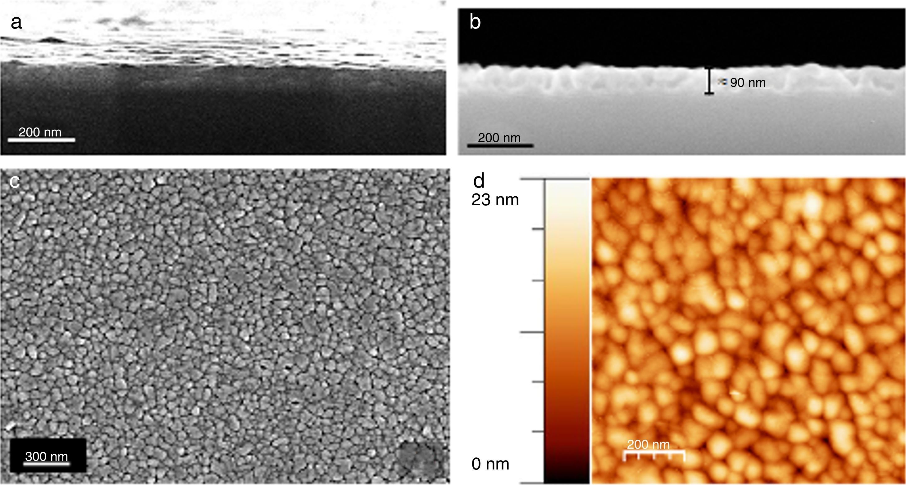
The microstructure of these SmBFO 5-layered films was investigated by FESEM and AFM. The cross-sectional micrograph in Fig. 4a shows a homogeneous film which is uniformly deposited along the whole substrate. The magnified micrograph in Fig. 4b evidences no trace of the individual layers (5 depositions), and instead a regular distribution of round-like shaped grains can be observed comprising the overall microstructure of the annealed film. An average thickness of 90nm is measured. The surface morphology is shown in Fig. 4c and as observed, the film exhibits a crack-free, uniform surface texture comprised by just one type of grains; for example, no square grains like those typically ascribed to big Bi2Fe4O9 mullite crystals [40,44] are observed through the whole sample. Also no discontinuous islands of material are ever detected in the grainy film [45], this being indicative of a homogeneous microstructure. To further check the uniformity of our aqueous solution-gel produced films, nanoscale morphological characterization was carried out using AFM. The obtained images showing the SmBFO film topography are depicted in Fig. 4d and once again a consistent film with a very uniform surface can be observed which yields an excellent roughness measurement of just around 3nm. An average grain size of around 70–80nm is also deduced from these images.
 and (b) Cross-section images evidencing a uniform deposition along the whole substrate with an average thickness of 90nm. (c) Top surface micrograph showing a homogeneous grain size distribution. (d) AFM image of the top surface (average grain size≈70–80nm).")
FESEM and AFM micrographs of the five-layers SmBFO thin film sample annealed at 600°C/1h. (a) and (b) Cross-section images evidencing a uniform deposition along the whole substrate with an average thickness of 90nm. (c) Top surface micrograph showing a homogeneous grain size distribution. (d) AFM image of the top surface (average grain size≈70–80nm).
The second set of experiments was conducted with the goal of obtaining SmBFO-SmBiT thin film composites. Fig. 5 shows the XRD of this annealed composite and as depicted a very similar XRD pattern is initially obtained. The only difference is the presence of four new diffraction maxima which can all be ascribed to the tetragonal Bi4Ti3O12 phase (ICDD file no. 047-0398). The peaks of this phase, and also those corresponding to BiFeO3, are again shifted to higher angles due to the incorporation of Samarium dopant into the respective lattices.
-layers SmBFO-SmBiT composite thin film sample after the annealing treatment at 600°C/1h. Open circles are assigned to the BiFeO3 phase, open squares to the Bi4Ti3O12, solid circles are assigned to the substrate signal and triangles to the secondary phase Bi2SiO5.")
XRD patterns of the (five plus five)-layers SmBFO-SmBiT composite thin film sample after the annealing treatment at 600°C/1h. Open circles are assigned to the BiFeO3 phase, open squares to the Bi4Ti3O12, solid circles are assigned to the substrate signal and triangles to the secondary phase Bi2SiO5.
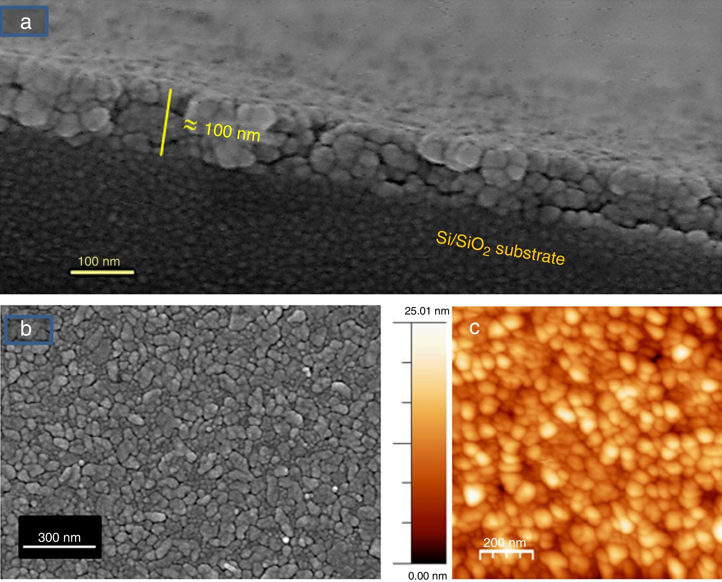
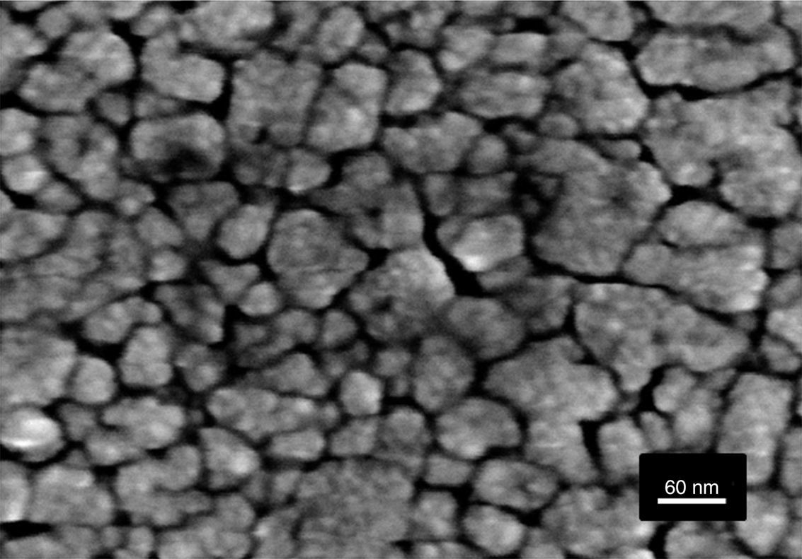
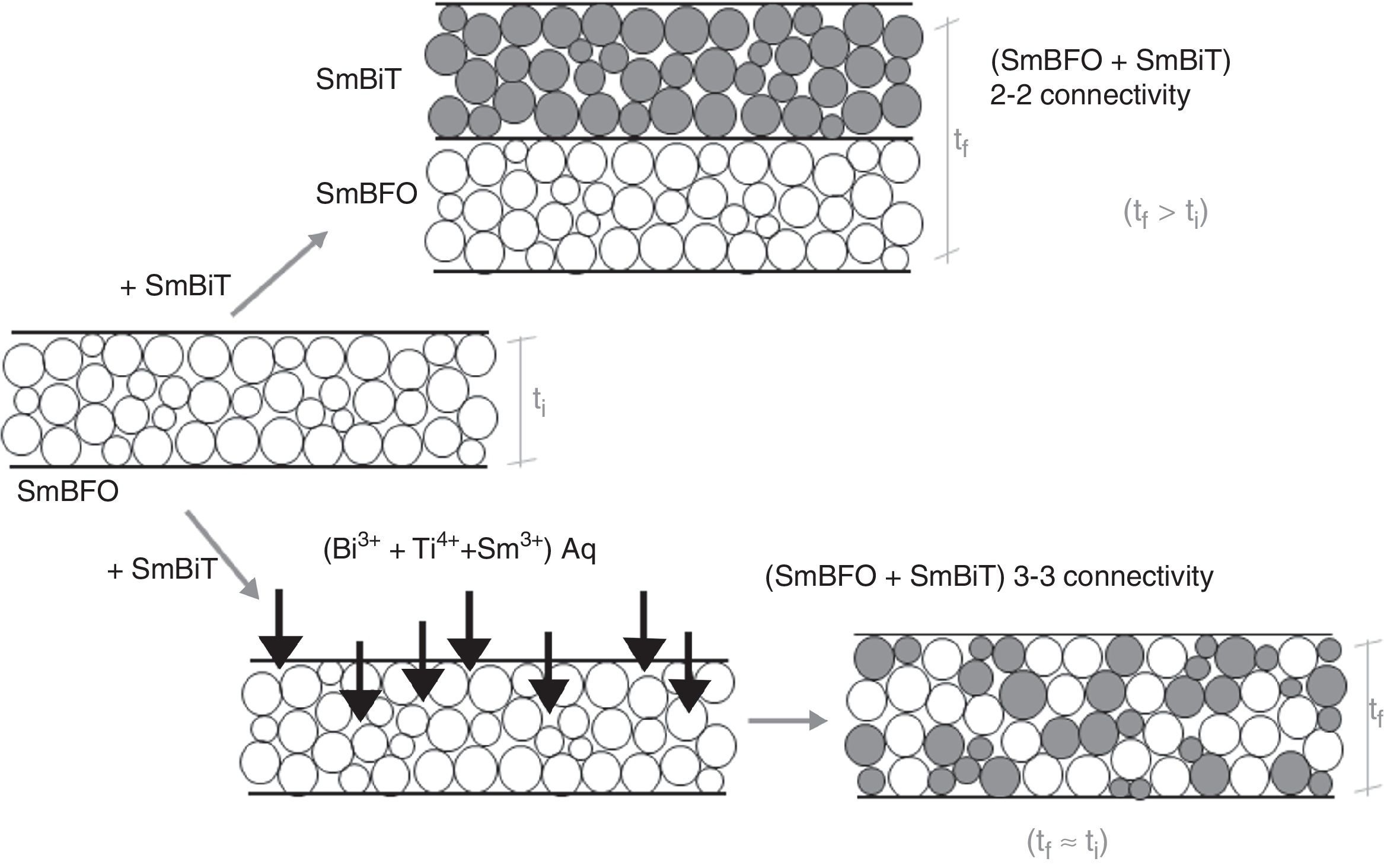
Fig. 6 shows the FESEM and AFM images of the annealed composite assembly and as observed the deposition is again quite uniform and continuous along the whole substrate, as occurred for the SmBFO sample. This time however some morphological differences appear in the sample, and these are particularly visible in the top surface micrograph (Fig. 6b): the deposition of the 5+5 layers produces a less homogeneous microstructure in which grains of an average size similar to the SmBFO grains in the previous sample are now surrounded by a number of smaller grains. In agreement with the XRD measurements no big crystals of Bi2Fe4O9 mullite can be observed all through the sample, so it is likely that those smaller grains may correspond to the SmBiT grains (unfortunately at this scale EDS cannot be used to confirm this assessment). On the other hand, the AFM topographic image in Fig. 6c evidences such decrease in homogeneity (compared with the AFM image in Fig. 4d) but still reveals a very uniform surface with a mean roughness again close to just 3nm. But besides that, in all this microstructural characterization depicted in Fig. 6 there is one specific parameter which greatly draws attention: as specified in Fig. 6a an average thickness of ca. 100nm is measured for the composite film. This is more or less the same thickness as in the previous 5-layered BFO film, which is quite striking because the composite film assembly comprises 5+5 deposited layers. In other words, after adding the SmBiT solution to the SmBFO counterpart we have doubled the number of deposited layers but the thickness of the film does not increase proportionally (it almost does not increase at all). The FESEM micrograph in Fig. 7 obtained from the top view surface of the five-layers SmBFO sample may serve to explain this behaviour. The illumination contrast in this picture (which is actually a magnification of the micrograph in Fig. 4c) has been slightly enhanced to intentionally highlight one interesting microstructural feature: as it can be seen in between the SmBFO grains there are nanometric channels, which would be indicating that despite the uniform aspect and apparent consistency of the film, it has not reached full density. In the composite, these channels in the SmBFO film allow the filtration (interpenetration) of the SmBiT precursor solution during the subsequent deposition steps, and then, on heating, Sm-Bi4Ti3O12 crystals form and grow inside the channels, thereby preventing a significant/proportional increase of the overall composite thickness. But moreover, this particular situation also leads to a different type of composite configuration, since both materials are now mixed in a sort of 3-3 connectivity, rather than the characteristic 2-2 connectivity of a bilayer system. This whole scenario is illustrated in Fig. 8, and somehow it also indicates how we can tune the suggested processing to prepare different types of composite configurations of this particular system. For example, an increase in the annealing temperature could probably aid to definitely close these channels in the starting SmBFO film and hence lead to a 2-2 connected layered material. One has to, however, take into consideration that this increase in annealing can result in the formation of unwanted secondary phases [40,41]. On the contrary we can proceed as described, and eventually obtain a 3-3 connectivity in a layer device.
-layers SmBFO-SmBiT composite thin film sample. (a) Cross-sectional FESEM image of the film showing an average thickness of 100nm. (b) FESEM image from the top of the surface this time evidencing a heterogeneous microstructure (two types of grains). (c) Corresponding AFM image of the surface.")
FESEM and AFM micrographs of the (five plus five)-layers SmBFO-SmBiT composite thin film sample. (a) Cross-sectional FESEM image of the film showing an average thickness of 100nm. (b) FESEM image from the top of the surface this time evidencing a heterogeneous microstructure (two types of grains). (c) Corresponding AFM image of the surface.


Schematic representation of the feasible mechanism leading to the obtaining of a 3-3 composite in a thin film geometry. Upper path: 2-2 connectivity that could be expected after depositing the SmBiT precursor solution over the SmBFO annealed layer. Lower path: obtained 3-3 connectivity, explained by the interpenetration of the SmBiT precursor solution through the open gaps/channels in the previously deposited SmBFO annealed layer.
Uniform and stable thin films of Sm-doped BiFeO3–Bi4Ti3O12 composite materials have been obtained by an aqueous solution-gel plus spin-coating deposition methodology. The complete procedure to dissolve the precursors of the metals of interest in an aqueous medium (hence avoiding the organic solvents typically used in a standard sol–gel process) and the subsequent deposition of the corresponding multimetal aqueous solutions by spin coating is systematically described. The microstructural characterization evidences the effectiveness of this simple method in producing layered composites with a precise control of the involved interfaces, with no need for high energy operations and/or sophisticated equipment. Furthermore by carefully controlling the experimental conditions, thin film composites with 3-3 type connectivity instead of the characteristic 2-2 connectivity of a bilayer system can be easily produced and at temperatures as low as 600°C.
This work was supported by the Spanish Ministry of Economy and Competitiveness, MINECO (Projects MAT2016-80182-R and MAT2014-59210-JIN). This work was also conducted in the frame of “Grupo de Propiedades Ópticas, Eléctricas y Magnéticas y sus Aplicaciones”, (UPM), Unidad Asociada al Instituto de Cerámica y Vidrio (CSIC).

